Device and method for improving wafer corrosion uniformity
A uniformity and wafer technology, which is applied in the field of devices for improving wafer corrosion uniformity, can solve problems such as wafer corrosion unevenness, achieve uniform wafer corrosion, improve wafer corrosion uniformity, and improve wafer middle thinness Effect
- Summary
- Abstract
- Description
- Claims
- Application Information
AI Technical Summary
Problems solved by technology
Method used
Image
Examples
Embodiment 1
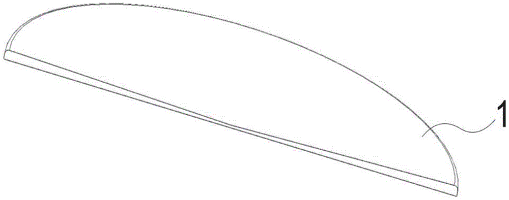
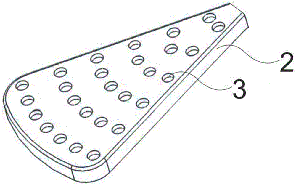
[0031] Please refer to figure 2 and Figure 4 A device for improving the uniformity of wafer corrosion provided by the present invention includes a wafer carrier (not shown in the figure), the upper end of the wafer carrier carries a wafer 1, and the wafer carrier includes a rotating mechanism and Fixing mechanism; the lower end of the wafer carrier is provided with at least one fan-shaped part 2, and the wafer carrier can rotate and drive the wafer 1 or the fan-shaped part 2. The fan-shaped part 2 is consistent with the radius of the wafer 1 and is in line with the The circle 1 is located on the concentric axis, and the surface of the fan-shaped part 2 is provided with spray holes 3 that can vertically spray liquid to the back of the wafer 1. The spray holes 3 are divided into different parts according to the direction of the fan-shaped part 2 from the center of the circle to the arc Sectors, the injection holes 3 of each sector are independently connected to the pipeline 4...
Embodiment 2
[0036] Please refer to figure 2 and Figure 5 , on the basis of Embodiment 1, the injection holes 3 in each area are connected to the two-way pipeline 4, and the two-way pipeline 4 is respectively provided with a valve 5 that can control the passage of the injection liquid, and the injection liquid is preferably ultrapure water ( UPW), the valve 5 on the first pipeline 41 controls the flow of hot ultrapure water (ie Hot UPW), and the valve 5 on the second pipeline 42 controls the flow of cold ultrapure water (ie Cold UPW).
[0037] In this embodiment, the flow rate of the hot spray liquid is constant, and the flow rate of the cold spray liquid gradually decreases according to the direction of the fan-shaped part 2 from the center of the circle to the arc. By controlling the flow rate of the cold spray liquid that each sector pipeline 4 passes through, the cold spray liquid is mixed with the hot spray liquid, so that the spray holes 3 of each sector are sprayed with spray liq...
Embodiment 3
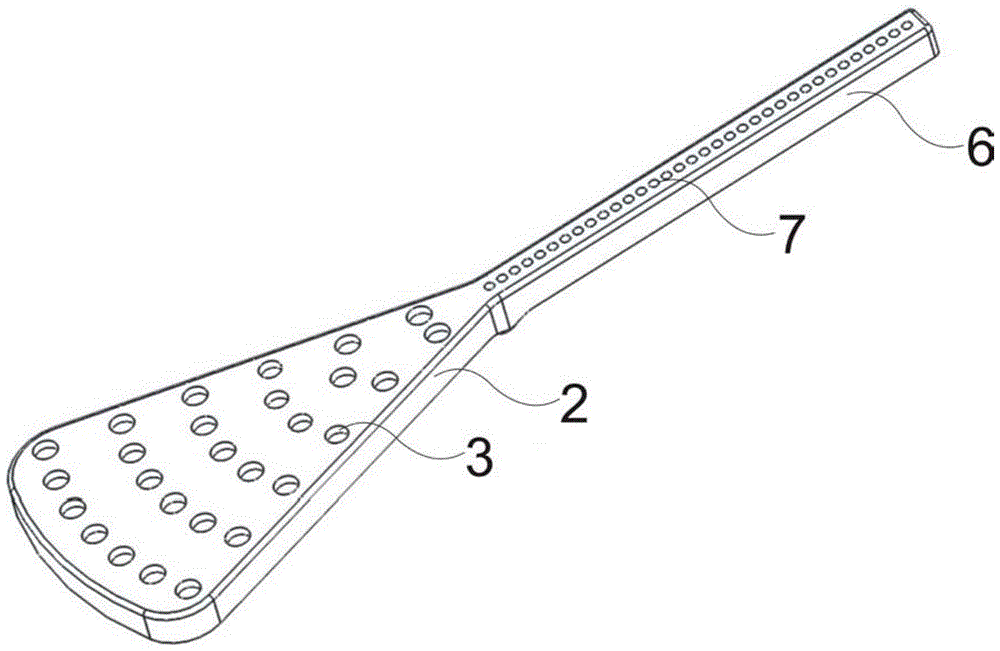
[0040] Please refer to image 3 , on the basis of Embodiment 1 or Embodiment 2, a bar-shaped body 6 is provided in the opposite direction of the center of the horizontal axis of the fan-shaped part 2, and the bar-shaped body 6 is connected with the center of the fan-shaped part 2, and the bar-shaped The body 6 is provided with several drying holes 7 for passing the drying gas. Preferably, the length of the strip 6 is consistent with the radius of the wafer 1, and the gas passing through the drying hole 7 is nitrogen.
[0041] In order to further improve the present invention, when the wafer 1 is installed on the rotating mechanism, the fan-shaped part 2 is installed on the fixing mechanism; the wafer 1 and the fan-shaped part 2 perform relative rotation, that is, the wafer 1 does Horizontal rotation movement, the fan-shaped part 2 is fixed, and the injection holes 3 on the fan-shaped part 2 vertically spray liquid to the back of the wafer 1 .
[0042] Or the fan-shaped part 2 ...
PUM
 Abstract
Description
Claims
Application Information
 - R&D
- Intellectual Property
- Life Sciences
- Materials
- Tech Scout
- Unparalleled Data Quality
- Higher Quality Content
- 60% Fewer Hallucinations
Browse by: Latest US Patents, China's latest patents, Technical Efficacy Thesaurus, Application Domain, Technology Topic, Popular Technical Reports.
© 2025 PatSnap. All rights reserved.Legal|Privacy policy|Modern Slavery Act Transparency Statement|Sitemap|About US| Contact US: help@patsnap.com


