
Rotor punching sheet for inner rotor permanent magnet motor

A permanent magnet motor and rotor punching technology, which is applied to the magnetic circuit rotating parts, magnetic circuit shape/style/structure, etc., can solve the problems of reducing the insulation capacity between sheets, reducing the mechanical strength of the rotor, and difficult processing

Inactive Publication Date: 2014-04-02
SHANDONG HUALI ELECTRIC MOTOR GRP
View PDF7 Cites 0 Cited by
  • Summary
  • Abstract
  • Description
  • Claims
  • Application Information

AI Technical Summary

Problems solved by technology

However, the smaller the width, the more difficult it is to process, and the mechanical strength of the rotor will also decrease. From the perspective of manufacturability and mechanical strength, the magnetic isolation magnetic bridge will not be made very narrow, so there will still be magnetic flux leakage at the position of the magnetic isolation magnetic bridge.
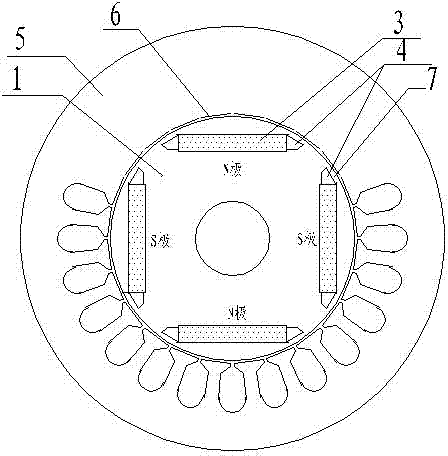
Usually the air gap 6 is formed by machining the outer circle of the rotor. Machining will reduce the insulation capacity between sheets and increase the eddy current loss caused by the harmonic magnetic field of the stator winding on the rotor surface.

Method used


Image

  • Rotor punching sheet for inner rotor permanent magnet motor
  • Rotor punching sheet for inner rotor permanent magnet motor
  • Rotor punching sheet for inner rotor permanent magnet motor

Examples


Embodiment 1

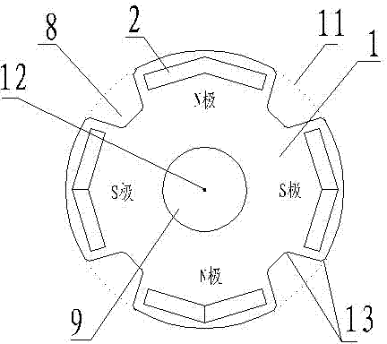
[0018] As attached image 3 As shown, a rotor punching piece of a 4-pole inner rotor permanent magnet motor. The rotor punching piece 1 is a ring-shaped piece. The middle hole of the ring-shaped piece body forms a shaft hole 9. There are 4 uniformly opened on the outer edge of the piece. The trapezoidal groove 8 has the bottom edge of the trapezoidal groove located at the outer edge of the sheet body, and a magnetic steel insertion hole 2 is provided on the sheet body between the two trapezoidal grooves, and the magnetic steel insertion hole 2 is close to the edge of the sheet body.

[0019] As attached image 3 As shown, in this embodiment, the contours of the outer edge of the sheet body between the two trapezoidal grooves are located on the same circular trace 11, and the circle in which the circular trace is located is concentric with the axis 12 of the annular sheet body.

[0020] From the above description, it can be seen that the rotor punching sheet is directly used to punch...

Embodiment 2

[0025] The rotor punch of the inner-rotor permanent magnet motor provided in Example 1 has a significantly improved performance in preventing magnetic flux leakage between poles compared with the rotor punch in the prior art. However, due to its use of round The ring-shaped sheet body is directly punched, and the outline of the outer edge of the sheet between the two trapezoidal grooves is located on the same circular track, resulting in the same thickness of the air gap of the motor. The structure can be seen attached Figure 5 Show air gap 6. In practical application tests, it is found that the uniform air gap structure is not conducive to weakening the cogging torque, and at the same time, it will increase the eddy current loss caused by the stator winding harmonic magnetic field on the rotor surface, which will have a greater impact on the overall performance of the motor.

[0026] In order to solve this problem, this embodiment implements further improvements on the basis of ...


PUM

PropertyMeasurementUnit
Angleaaaaaaaaaa

Abstract

The invention belongs to the field of motor manufacturing. In order to overcome the technical problems of the rotor punching sheets of the inner rotor permanent magnet motor used in the prior art, the invention provides a rotor punching sheet for an inner rotor permanent magnet motor. The rotor punching sheet comprises an annular sheet body, wherein a middle hole of the annular sheet body forms a shaft hole. The rotor punching sheet is characterized in that trapezoidal grooves corresponding to the pole numbers of the motor are uniformly formed in the outer edge of the sheet body, the bottom edges of the trapezoidal grooves are positioned at the outer edge of the sheet body, and magnetic steel inserting holes are formed in the sheet body between the two trapezoidal grooves and are near the edge of the sheet body. Compared with the traditional rotor punching sheet, the rotor punching sheet of the inner rotor permanent magnet motor has the advantages that the magnet leakage prevention effect is obviously improved, and the obvious promotion effect is realized on the further improvement of the motor performance.

Description

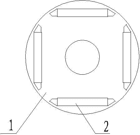
Technical field [0001] The invention belongs to the field of motor manufacturing, and relates to a rotor punching sheet of an inner rotor permanent magnet motor. Background technique [0002] At present, the rotor punching structure of the inner rotor permanent magnet motor is as attached figure 1 Shown, attached figure 1 Shown is a rotor punch 1 of a 4-pole inner rotor permanent magnet motor, which includes a circular punch body, and the punch body near the outer circle is evenly provided with magnetic steel inserts corresponding to the number of motor poles. Hole 2. Attached figure 2 As shown, the width of the magnetic steel insertion hole 2 is greater than that of the magnetic steel 3. The magnetic steel insertion hole gaps on both sides of the magnetic steel 3 form a magnetic isolation air gap 4, and the gap between the rotor punch 1 and the stator punch 5 forms an air gap. Gap 6, the punching piece body between the two ends of the magnetic steel insertion hole and the roto...

Claims


Application Information

Patent Timeline
IPC IPC(8): H02K1/27
Inventor 李海成尹志华王庆东
Owner SHANDONG HUALI ELECTRIC MOTOR GRP
Learn More