
Seawater osmosis filtration method and osmosis water intake unit

一种过滤方法、水单元的技术,应用在逆渗透、过滤分离、过滤处理等方向,能够解决初始费用高、工程规模变大、工程规模大等问题,达到维护容易、工程规模变小的效果

Active Publication Date: 2016-08-17
HITACHI ZOSEN CORP +1
View PDF7 Cites 0 Cited by
  • Summary
  • Abstract
  • Description
  • Claims
  • Application Information

AI Technical Summary

Problems solved by technology

This indirect water intake method does not have the problems of the direct water intake method at all, but due to the high initial cost and the problem of reduced water intake due to the clogging of the mesh on the permeable surface, the spread of the method is slow.
[0008] However, in the osmotic water intake method proposed in the above-mentioned Patent Document 1, the seawater infiltration water intake rate is 1 to 8 m / day, which is a very slow filtration rate. Therefore, in order to extract a large amount of seawater in a short time, a large area is required. Larger project scale (technical problem 1)
Therefore, it is possible to reduce the seawater infiltration rate by only removing the suspended matter accumulated on the surface of the sand filter layer.
[0014] In addition, for example, in the infiltration water intake method of Patent Document 1, a support gravel layer 5a is formed at the excavation part of the seabed, and the water intake pipe 6 is buried, and a support gravel layer 5b and filter sand 5c are formed on the top of the support gravel layer 5a. At the same time, Backfilling to the seabed surface again, the above-mentioned works are all carried out on the seabed site, so the scale of the installation project is large

Method used


Image

  • Seawater osmosis filtration method and osmosis water intake unit
  • Seawater osmosis filtration method and osmosis water intake unit
  • Seawater osmosis filtration method and osmosis water intake unit

Examples


Embodiment

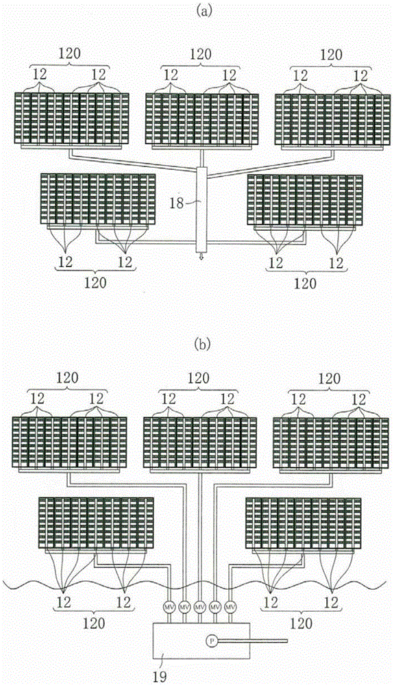
[0049] Next, use Figure 1 to Figure 13 , the embodiments of the present invention will be described in detail.

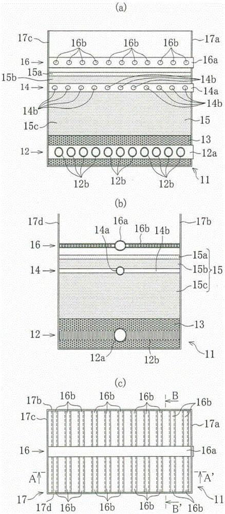
[0050] figure 1 It is a figure which shows an example of the permeation water intake unit 11 used for the seawater permeation filtration method of this invention.

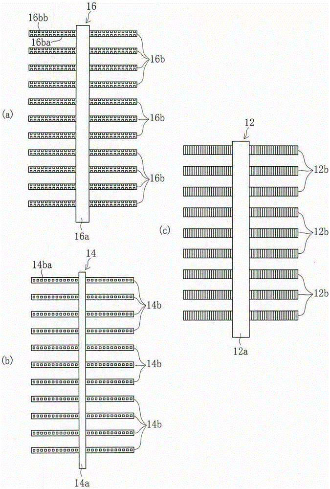
[0051] exist figure 1 In (a) and (b), 12 indicates that it is composed of a main pipe 12a and a plurality of branch pipes 12b branched in a direction intersecting with the main pipe 12a, and is buried in a deep gravel layer 13 for forming a sand filter layer on the seabed water pipes. In the sand layer 15 for forming the sand filter layer intermediate layers 15b, 15c and the surface layer 15a, a backwash pipe 14 composed of a main pipe 14a and a plurality of branch pipes 14b divided in a direction crossing the main pipe 14a is embedded.

[0052] exist figure 1 In (c), 16 has shown the water suction pipe which consists of the main pipe 16a and the some branch pipe 16b. Supervisor 16a AS figure...


PUM


Abstract

The present invention provides a seawater infiltration filtration method and a infiltration water intake unit, which cleans the surface layer of the sand filter layer and the suspended matter introduced into the middle layer. The seawater infiltration filtration method of the invention pre-forms the infiltration water intake unit (11) , the infiltration water intake unit is buried in the water intake pipe (12) in the deep gravel layer (13) used to form the sand filter layer, and is buried in the backwash layer (15) in the middle layer and surface layer used to form the sand filter layer. Pipe (14), a water suction pipe (16) is provided above the sand layer (15). A required number of infiltration water intake units (11) are combined at a location on the seabed to form a sand filter layer, and seawater that naturally penetrates from the sea along the sand filter layer is introduced into the water intake pipe (12) to draw seawater. The seawater penetration rate is set to 400m / day or less. Spray water or air from the backwash pipe (14) to stir the suspended matter introduced into the middle layer of the sand filter layer, causing it to roll up on the upper surface of the sand filter layer, and suck the stirring water from the water suction pipe (16) for recovery . The present invention can maintain the seawater penetration speed as high as possible, which is less than or equal to 400m / day.

Description

technical field [0001] The present invention relates to a filtration method and an infiltration water intake unit. The filtration method is a filtration method for water intake of seawater permeated from the sand layer on the sea bottom. The infiltration water intake unit is used for implementing the filtration method and has the function of backwashing. Pipe, etc., the backwashing pipe removes the organisms or suspended substances accumulated on the surface of the sand layer and introduced into the middle layer to prevent the clogging of the screen mesh. Background technique [0002] As a method of taking water from seawater, most of the methods such as Figure 14 As shown, for example, a direct water intake method is used to draw water from seawater from a water intake 1 arranged on the seabed through an aqueduct 2 . also, Figure 14 3 is a pump for taking water from seawater, and 4 is a reverse osmosis membrane device. [0003] However, in the direct water intake method,...

Claims


Application Information

Patent Timeline
Patent Type & Authority Patents(China)
IPC IPC(8): B01D24/02B01D24/46B01D24/48B01D29/60B01D29/62B01D29/66E03B3/04
CPCC02F1/004C02F1/441C02F2103/08B01D61/04B01D2311/04B01D2311/2649Y02A20/131E03B3/04
Inventor 新里英幸井上隆之荒井浩成向井清和三村等
Owner HITACHI ZOSEN CORP
Learn More