
Temperature controllable cryogenic cooling device

A cooling device and low-temperature technology, applied in metal processing machinery parts, maintenance and safety accessories, metal processing equipment, etc., can solve the problems of reducing the fatigue strength of parts, large deformation, and the cooling effect is difficult to meet the processing requirements, etc., to solve the problem of milling , the cooling effect is remarkable

Active Publication Date: 2016-03-02
TECHNICAL INST OF PHYSICS & CHEMISTRY - CHINESE ACAD OF SCI
View PDF6 Cites 2 Cited by
  • Summary
  • Abstract
  • Description
  • Claims
  • Application Information

AI Technical Summary

Problems solved by technology

[0002] In the process of mechanical processing, due to the wide variety of materials, for some special difficult-to-machine materials, the milling method at room temperature has certain limitations and cannot meet the processing requirements.
For example, metal niobium has ductility at room temperature, and large deformation can be achieved without intermediate heat treatment, but a large amount of heat will be generated during milling, which makes it easy to stick to the knife during processing. Rotating together seriously affects the surface quality of the workpiece; the chemical activity of titanium metal is high, and at high cutting temperatures, it is easy to absorb oxygen and nitrogen elements in the air to form a hard and brittle outer skin, and at the same time, plastic deformation during cutting It will also cause surface hardening, and the chilling phenomenon will not only reduce the fatigue strength of the parts, but also increase the wear of the tool, which is a major defect in the cutting of titanium alloys
[0003] At present, most milling equipment on the market use cutting fluid or air cooling technology to cool the workpiece. The temperature of the cooling medium is only between -50°C and normal temperature, and the actual cooling effect is difficult to meet the processing needs.

Method used


Image

  • Temperature controllable cryogenic cooling device

Examples


Embodiment Construction

[0020] The specific implementation manner of the invention will be further described below in conjunction with the accompanying drawings and embodiments.

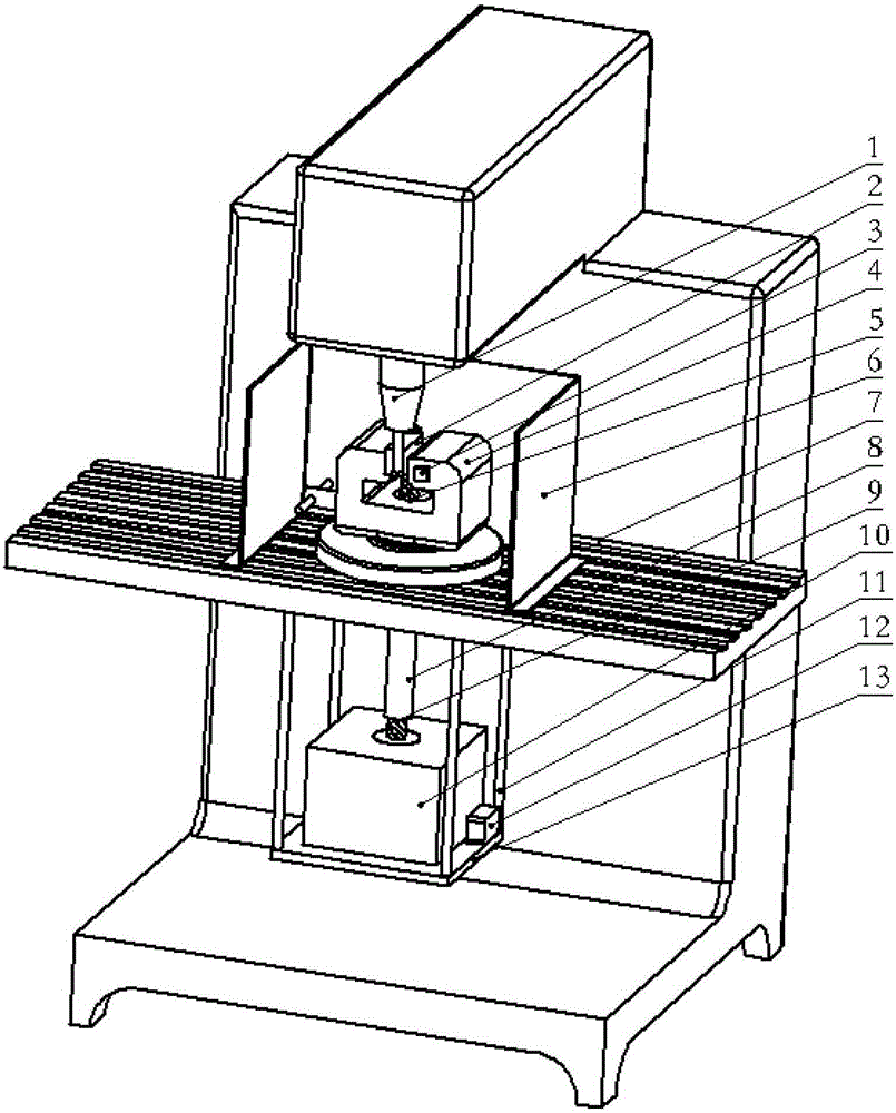
[0021] like figure 1 A temperature-controllable cryogenic cooling device shown includes a fixture 4, a heat transfer member connected to the fixture 4, and a liquid nitrogen container 10 connected to the heat transfer member; the fixture 4 is preferably made of a material with good thermal conductivity, such as a copper fixture , the specifications can be selected according to the actual clamping requirements, mainly used for good heat conduction while clamping the processed material 2; the liquid nitrogen in the liquid nitrogen container 10 is used to absorb a large amount of heat during vaporization, thereby cooling the heat transfer member, The thermal component cools the processed material 2 clamped by the fixture 4 through heat conduction, and at the same time takes away the heat generated during milling, which solves ...


PUM


Abstract

The invention relates to the field of mechanical manufacturing, in particular to a temperature-controllable cryogenic cooling device which comprises a fixture, a heat transfer component and a liquid nitrogen container. The fixture is used for clamping a machined material, the heat transfer component is connected with the fixture, and the liquid nitrogen container is connected with the heat transfer component; liquid nitrogen in the liquid nitrogen container is vaporized, absorbs heat and cools the heat transfer component, the heat transfer component cools the machined material by means of heat transfer, and the machined material is clamped by the fixture. The temperature-controllable cryogenic cooling device has the advantages that a large quantity of heat can be absorbed by the aid of vaporization of the liquid nitrogen, the machined material clamped by the fixture is cooled by the heat transfer component with an excellent heat conducting property, and the heat generated during milling machining can be taken away; an obvious cooling effect can be realized, the lowest temperature of the temperature-controllable cryogenic cooling device can reach the temperature of the liquid nitrogen, and accordingly certain materials which are difficult to machine under room-temperature conditions can be effectively milled.

Description

technical field [0001] The invention relates to the field of mechanical manufacturing, in particular to a temperature-controllable low-temperature cooling device. Background technique [0002] In the machining process, due to the wide variety of materials, for some special difficult-to-machine materials, the milling method at room temperature has certain limitations and cannot meet the processing requirements. For example: metal niobium has normal temperature ductility, and it can achieve large deformation without intermediate heat treatment, but it will generate a lot of heat during milling, which makes it easy to stick to the knife during processing. Rotating together seriously affects the surface quality of the workpiece; the chemical activity of titanium metal is high, and at high cutting temperatures, it is easy to absorb oxygen and nitrogen elements in the air to form a hard and brittle outer skin, and at the same time, plastic deformation during cutting It will also ...

Claims


Application Information

Patent Timeline
Patent Type & Authority Patents(China)
IPC IPC(8): B23Q11/10
CPCB23Q11/1053
Inventor 曾翔宇孟祥敏
Owner TECHNICAL INST OF PHYSICS & CHEMISTRY - CHINESE ACAD OF SCI
Learn More