Milling machine mechanism special for inner surface of annular workpiece

A ring-shaped workpiece and inner surface technology, which is applied in the field of milling machines, can solve problems such as low machining accuracy, inability to accurately complete positioning operations, time-consuming and labor-intensive inner surfaces of ring-shaped workpieces, and achieve the effects of increased production efficiency, improved positioning accuracy, and reduced production costs.

Active Publication Date: 2018-09-14
广州鑫利华精工五金有限公司
View PDF10 Cites 0 Cited by
  • Summary
  • Abstract
  • Description
  • Claims
  • Application Information

AI Technical Summary

Problems solved by technology

Although there are many types of milling machines at present, the milling operation on the inner surface of the annular workpiece is still time-consuming and laborious, the machining accuracy is low, and the positioning operation cannot be completed accurately

Method used


Image

  • Milling machine mechanism special for inner surface of annular workpiece
  • Milling machine mechanism special for inner surface of annular workpiece
  • Milling machine mechanism special for inner surface of annular workpiece

Examples


Embodiment 1

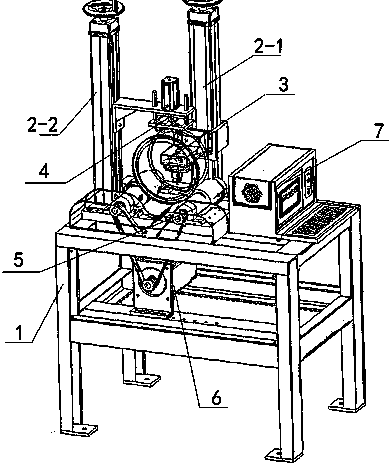
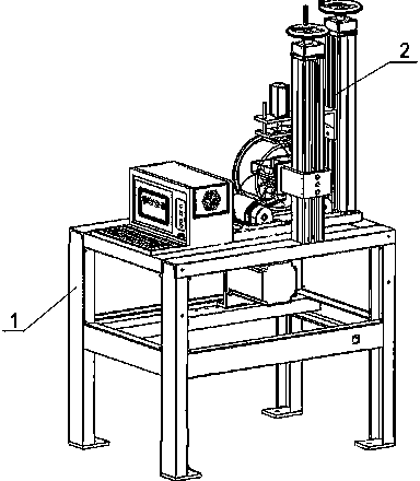
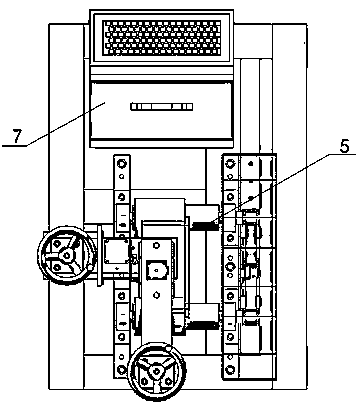
[0027] Embodiment 1: This embodiment discloses a milling machine mechanism dedicated to the inner surface of a ring-shaped workpiece. The milling machine mechanism includes a frame 1, a column 2 is arranged on the frame, and a milling cutter assembly 3 and a pressing assembly 4 are arranged on the column 2. , wherein the column 2 includes a first column 2-1 and a second column 2-2, slide rails are provided on the first column 2-1 and the second column 2-2, and the milling cutter assembly 3 is slidably arranged on the second column On a column 2-1, the pressing assembly 4 is slidably arranged on the second column 2-2, and the milling cutter assembly 3 includes a plate set 3-1 matched with the slide rail of the first column, and the plate set 3-1 The front end is fixed with a receiving plate 3-2, and the receiving plate 3-2 is fixedly connected with a milling cutter control box 3-3. The milling cutter control box 3-3 is provided with an electrical control component, and the milli...

Embodiment 2

[0041] Embodiment 2: This embodiment discloses the method of using the milling machine mechanism on the inner surface of the annular workpiece in Embodiment 1. Specifically, the steps of using the milling machine mechanism are as follows:

[0042] A. Operate the driving device on the first column, so that the milling cutter assembly moves down to a suitable distance along the column, place the annular workpiece to be operated between the two rolling wheels through the milling cutter assembly, and adjust the position.

[0043] B. Operate the driving device on the second column to make the pressing assembly move down along the column. When the rolling wheel is at an appropriate distance from the upper surface of the workpiece, the pressing motor is turned on. With the cooperation of the sliding column, the pressing motor stretches. The rod drives the bearing frame to move downward, and the two rolling wheels on the bearing frame are pressed on the upper surface of the workpiece...


PUM

PropertyMeasurementUnit
Particle sizeaaaaaaaaaa

Abstract

The invention discloses a milling machine mechanism special for the inner surface of an annular workpiece. The milling machine mechanism solves the problem that the inner surface of the annular workpiece cannot be milled. The milling machine mechanism is provided with a milling cutter assembly, a pressing and holding assembly, a bearing assembly and a CCD camera, and the problem about milling of the inner surface of the annular workpiece is solved. A rolling wheel is arranged, the workpiece positioning precision is greatly improved, and the operation cost is greatly reduced. Bodies of rollingbearing wheels of the bearing assembly are coated with crystallite abrasive materials, the inner surface of the annular workpiece can be subjected to milling treatment, the outer surface can be subjected to polishing treatment, one machine has dual purposes, the production efficiency is obviously improved, and the production cost is obviously reduced.

Description

technical field [0001] The invention relates to the field of milling machines, and more specifically relates to a milling machine mechanism dedicated to the inner surface of a circular workpiece. Background technique [0002] Mechanical processing is a key component of the manufacturing industry. Industries related to national security and people's daily life, such as aerospace, automobiles, ships, rail transit, and health care, are almost inseparable from mechanical processing products. However, 90% of the machining workload is cutting (including grinding), and cutting is still an important part of machining and manufacturing in the 21st century. As the basic technological equipment, machine tools and their cutting tools play a key role in cutting processing. [0003] A milling machine is a machine tool with a wide range of uses. It can process planes (horizontal planes, vertical planes), grooves (key slots, T-shaped slots, dovetail slots, etc.), toothed parts (gears, spli...

Claims


Application Information

Patent Timeline
IPC IPC(8): B23C3/06B23P23/04B23Q3/06
CPCB23C3/06B23P23/04B23Q3/062
Inventor 荀为君
Owner 广州鑫利华精工五金有限公司
Why Eureka
Try Eureka