

Large-angle all-round-lighting LED bulb
A technology of LED light bulbs and large angle, applied in the field of lighting, can solve the problems of LED light efficiency reduction, heavy weight, high temperature, etc., and achieve the effect of ideal heat dissipation, light weight, and optimized space arrangement
- Summary
- Abstract
- Description
- Claims
- Application Information
AI Technical Summary
Problems solved by technology
Method used
Image

Examples
Embodiment Construction
[0024] The specific embodiment of the present invention will be further described in detail below in conjunction with the accompanying drawings.
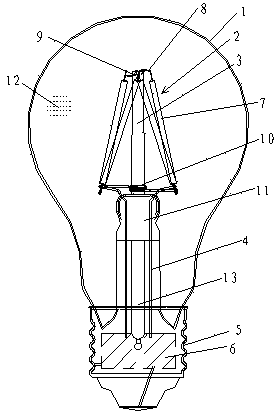
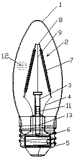
[0025] A large-angle full-circumference LED light bulb according to the present invention is composed of a sealed light-emitting bulb 1, a sealing part 11 that seals and seals the bottom opening of the light-emitting bulb, a light-emitting module 2, and a lamp cap connected to the bottom of the sealing part. Group 2 is a strip-shaped LED omnidirectional filament 7, which is installed vertically above the sealing part, and a gas pipe (13) is arranged inside the sealing part. The strip-shaped LED omnidirectional filament 7 is connected to the power supply lead 4 contacts of the sealing part through a connecting wire , the inside of the sealed luminous bulb is filled with heat dissipation protection gas 12, and the heat dissipation protection gas (12) is hydrogen or inert gas or a mixture of both.
[0026] The lamp head is used to conn...
PUM
 Abstract
Description
Claims
Application Information