La-Fe-based magnet with double hard-magnetic main phases and preparation method for same

A dual hard magnetic main phase, double main phase technology, applied in the direction of magnetic objects, inductance/transformer/magnet manufacturing, magnetic materials, etc., can solve the problems of deteriorating magnet performance, achieve cost-effective, good magnetic performance, and reduce production costs Effect

Active Publication Date: 2014-04-09
CENT IRON & STEEL RES INST
View PDF7 Cites 16 Cited by
  • Summary
  • Abstract
  • Description
  • Claims
  • Application Information

AI Technical Summary

Benefits of technology

This patented technical effect lies within this patents' unique features - it allows us to create high flexibility in compositional tunings without requiring expensive materials such as neodymium (Nd), which makes up about 75% of our worldwide supply). Additionally, there is no limitation on how much we use these types of fastening devices like screws because they don’t require too many times during their lifespan compared to regular tools made of iron powder. Overall, this innovative material provides better quality products at lower costs while still having excellent magnesistency characteristics over longer periods of usage.

Problems solved by technology

This patented technical problem addressed in this patent relates to improving the properties of LFO-, cathode ray tube type memory devices used today without compromising their function due to excessive consumption of expensive metals such as lanthum. Current solutions involve adding extra elements like ceramic powder or iron oxide instead of pure rare earth, resulting in decreased efficiency and longer lifetimes of these memories. There is currently a new solution involving combining various elemental compositions together through fast setting processes.

Method used


Image

  • La-Fe-based magnet with double hard-magnetic main phases and preparation method for same
  • La-Fe-based magnet with double hard-magnetic main phases and preparation method for same
  • La-Fe-based magnet with double hard-magnetic main phases and preparation method for same

Examples


Embodiment Construction

[0033] The specific implementation manners of the present invention will be further described in detail below in conjunction with the accompanying drawings and embodiments.

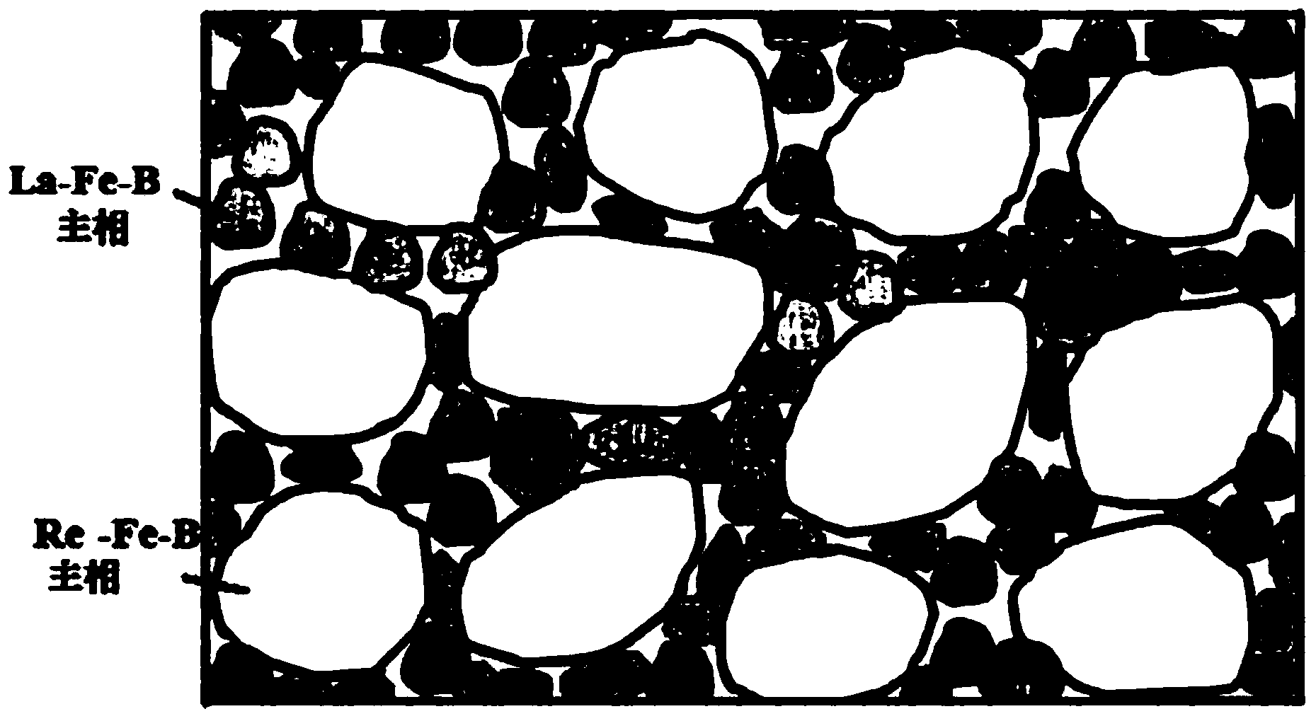
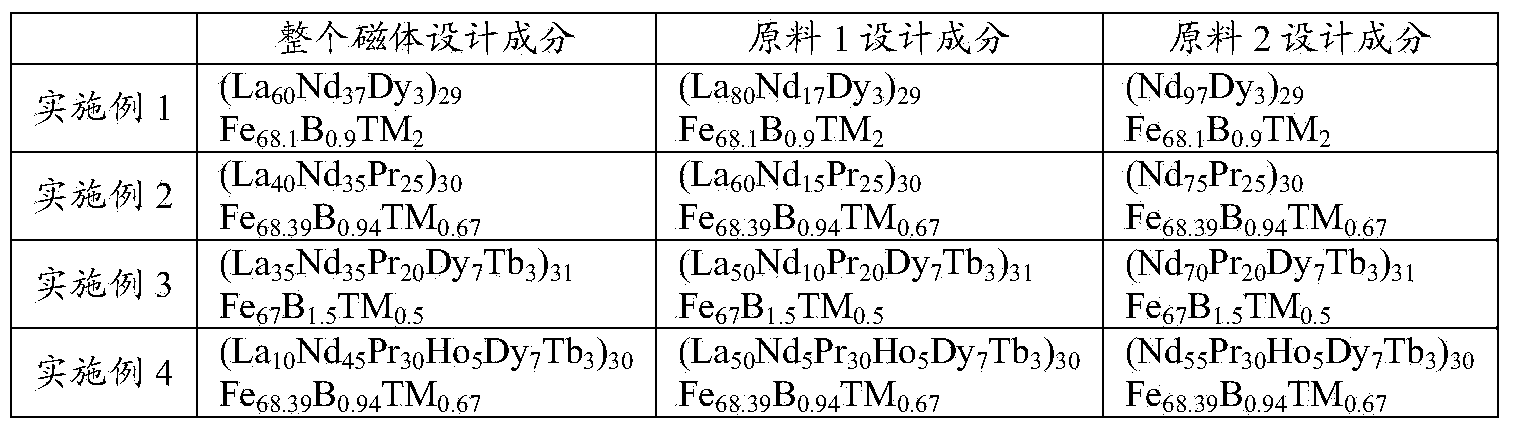
[0034] The composition chemical formula of the whole magnet design is (La x Re 100-x ) a Fe 100-a-b-c B b tm c , where x, a, b and c represent the mass percentage of the corresponding elements, Re is one or more of Nd, Pr, Dy, Tb, Ho elements, TM is Ga, Co, Cu, Nb, Al elements One or more of them (as shown in Table 1).

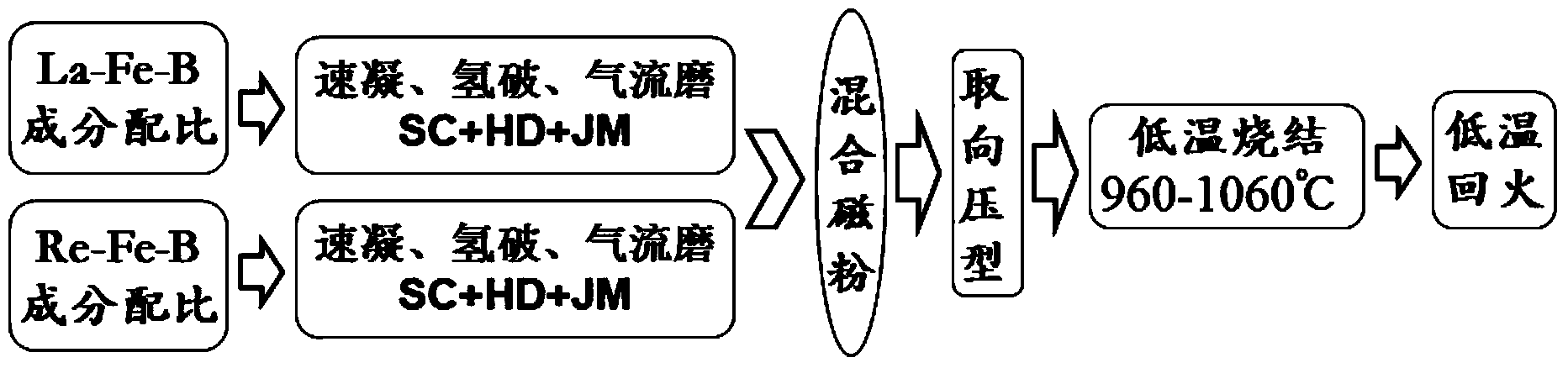
[0035] Step 1: prepare two kinds of raw materials respectively according to the composition chemical formula of mass percent as shown in table 1: (La x1 Re 100-x1 ) a Fe 100-a-b-c B b tm c (wt.%) and Re a Fe 100-a-b-c B b tm c (wt.%), where x, a, b and c respectively represent the mass percentage of the corresponding element, 50%≤x1≤80%, 29%≤a≤31%, 0.9%≤b≤1.5%, 0.5%≤c ≤2%, TM is one or more of Ga, Co, Cu, Nb, Al elements;

[0036] Table 1 Alloy composition chemical formul...


PUM

PropertyMeasurementUnit
Granularityaaaaaaaaaa

Abstract

The invention discloses a novel La-Fe-based magnet with double hard-magnetic main phases and a preparation method for the same, which belong to the technical field of rare-earth permanent magnet materials. The chemical formula of the magnet is expressed to be (LaxRe100-x)aFe100-a-b-cBbTMc, wherein x, a, b and c are used for representing the mass percentages of corresponding elements, moreover, x is not less than 10% and not greater than 60%, a is not less than 29% and not greater than 31%, b is not less than 0.9% and not greater than 1.5%, and c is not less than 0.5% and not greater than 2%; Re is one or several of elements Nd, Pr, Dy, Tb and Ho, and TM is one or several of elements Ga, Co, Cu, Nb and Al. In the magnet disclosed by the invention, La occupies the highest weight in the various rare-earth elements, the content of Nd is less than or equal to 50% of the total of the rare-earth elements, heavy-rare-earth elements are less or not used for general magnets, and an appropriate amount of heavy rare earth needs to be added for preparing high-coercivity magnets. According to the magnet disclosed by the invention, ingredient proportioning is performed by mixing rare earth, thus reducing the cost increased by separation and purification for the rare earth, and rapidly-hardened alloy sheets only needing two ingredients are used for preparing powder by an air-flow mill. According to the magnet and the preparation method disclosed by the invention, a low-temperature sintering technology is used, the sintering temperature is 960-1060 DEG C and tempering is performed at a low temperature; two main phases with different magneto-crystalline anisotropy constants K are contained in the magnet.

Description


Claims


Application Information

Patent Timeline
Owner CENT IRON & STEEL RES INST
Why Eureka
Try Eureka