Fly-back converter circuit

A technology of flyback converter and circuit, which is applied in the direction of instruments, DC power input conversion to DC power output, electrical components, etc. It can solve the problems of weak reliability, large loss, complicated control process, etc., and reduce the shutdown voltage , The circuit constitutes a simple effect

Inactive Publication Date: 2014-04-09
SIEMENS AG
View PDF7 Cites 2 Cited by
  • Summary
  • Abstract
  • Description
  • Claims
  • Application Information

AI Technical Summary

Problems solved by technology

figure 1 The switching circuit shown is simple in structure and easy to implement, but has the following disadvantages: the main switching device Q1 has to withstand a turn-off voltage of about twice the voltage of the DC bus voltage when it is turned off; and the start-up resistor R1 is always connected to the high-voltage circuit In the normal operation of the flyback converter circuit, the power consumption is still consumed, and the loss is large, which reduces the overall working efficiency of the circuit.
This circuit can realize the automatic exit of the bootstrap circuit, but the circuit is controlled by a relay and switched by mechanical contacts, the reliability is weak, and there are many circuit components, the control process is complicated

Method used


Image

  • Fly-back converter circuit
  • Fly-back converter circuit
  • Fly-back converter circuit

Examples


Embodiment Construction

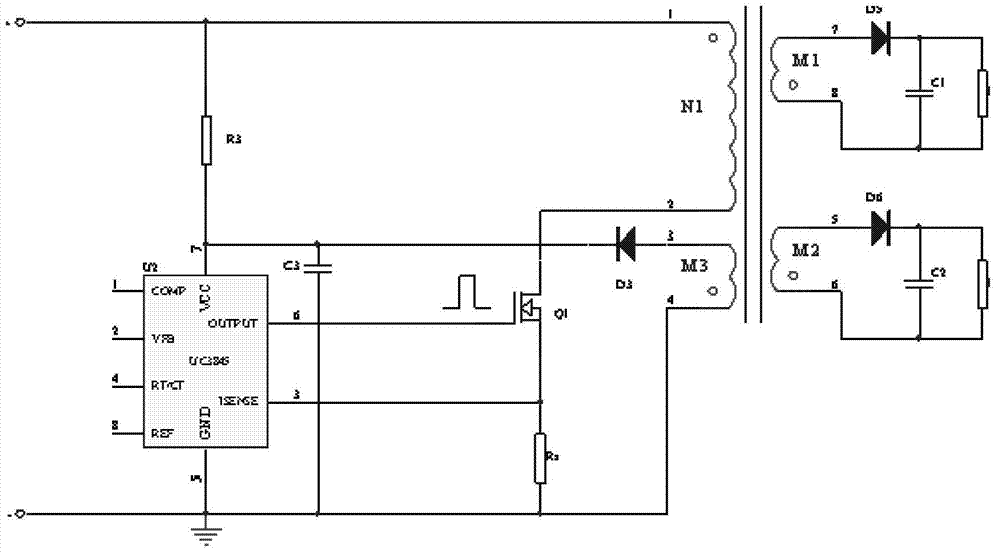
[0020] According to the flyback converter circuit of the embodiment of the present invention, a plurality of controllable switching devices are used as the main switching device so that the DC bus voltage is intermittently provided to the transformer, and the switching of each of the plurality of controllable switching devices The off voltage is clamped by the diode to a voltage not greater than the DC bus voltage, thereby reducing the off voltage borne by the main controllable switching device.

[0021] In the following, various embodiments of the present invention will be described in detail with reference to the accompanying drawings.

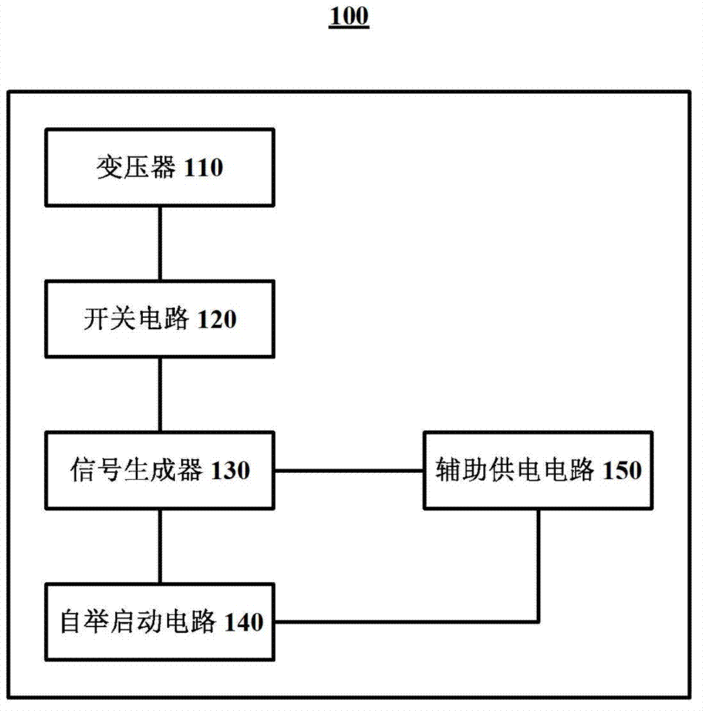
[0022] see now image 3 , which shows a block diagram of a flyback converter circuit according to an embodiment of the present invention. like image 3 As shown, the flyback converter circuit 100 may include a transformer 110 , a switch circuit 120 , a signal generator 130 , and a bootstrap startup circuit 140 . Preferably, an auxiliary p...


PUM


Abstract

The invention relates to a fly-back converter circuit. The fly-back converter circuit comprises a transformer for outputting load voltages which can be used for a load according to DC busbar voltages, a switch circuit used for alternative conduction and switching-off according to pulse width modulation signals to enable the DC busbar voltages to be interruptedly supplied to the transformer, a signal generator for generating the pulse width modulation signals according to the voltages of the load and the currents of the switch circuit when being supplied with working voltages, and a bootstrap starting circuit for supplying the signal generator with the working voltages during the starting period of the fly-back converter circuit, wherein the switch circuit comprises multiple controllable switch devices and multiple diodes, the multiple controllable switch devices are alternatively conducted and switched off simultaneously according to the pulse width modulation signals, and when the multiple controllable switch devices are switching-off states, the switched-off voltages of the multiple controllable switch devices are clamped by one of the clamps of the multiple diodes to be voltages not greater than the DC bulbar voltages. By use of the fly-back converter circuit, the switching-off voltages born by a main switch device during switching-off can be reduced.

Description

technical field [0001] The invention relates to a flyback converter circuit. Background technique [0002] Flyback converter circuit, also known as single-ended flyback switching circuit or single-ended flyback switching voltage, is a circuit that uses power electronics technology to control the conduction duty cycle of controllable switching devices to output a stable voltage. It is characterized by small size, light weight and high efficiency. Due to the simple structure of the flyback converter circuit and the easy realization of multi-channel voltage output through the transformer, the flyback converter circuit is widely used in various occasions requiring multiple output voltages. [0003] figure 1 A conventional flyback converter circuit is shown. like figure 1 As shown, when the flyback converter circuit is connected to the DC bus power supply, the DC bus power supply charges the capacitor C3 through the startup resistor R3, and when the voltage of the capacitor C...

Claims


Application Information

Patent Timeline
Patent Type & Authority Applications(China)
IPC IPC(8): H02M3/335H02M1/36
Inventor 廖华李晶
Owner SIEMENS AG
Why Eureka
Try Eureka