
Power control apparatus for high-frequency dielectric heating

A technology of power control and high-frequency medium, which is applied in the field of power control devices for high-frequency medium heating, can solve problems such as excessive voltage and component damage, and achieve the effect of shortening time and high reliability

Active Publication Date: 2014-04-09
PANASONIC CORP
View PDF5 Cites 14 Cited by
  • Summary
  • Abstract
  • Description
  • Claims
  • Application Information

AI Technical Summary

Problems solved by technology

Therefore, the voltage applied to the secondary-side rectifier circuit 111 is likely to be too large, and parts may be damaged.

Method used


Image

  • Power control apparatus for high-frequency dielectric heating
  • Power control apparatus for high-frequency dielectric heating
  • Power control apparatus for high-frequency dielectric heating

Examples


Embodiment approach 1

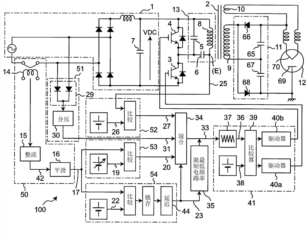
[0084] figure 1 A high-frequency dielectric heating device according to Embodiment 1 of the present invention showing an inverter power circuit with a two-transistor bridge arm structure for driving a magnetron as a microwave generating device and controlling the operation of the inverter power circuit. Power control device. In Embodiment 1, an inverter power supply circuit having a two-transistor arm structure was described, but the present invention can also be applied to an inverter power supply circuit including a plurality of transistors.

[0085] Such as figure 1 As shown, in the inverter power supply circuit of the double-transistor bridge structure, the main circuit on the primary side of the flux leakage transformer 2 consists of a DC power supply circuit 1, a flux leakage transformer 2, a first semiconductor switching element 3, and a second semiconductor switch The element 4 , the first capacitor 5 , the second capacitor 6 , and the third capacitor 7 (smoothing ...


PUM


Abstract

In order to prevent an excessive voltage from being applied to a magnetron and a rectifier circuit on a secondary side of a leakage transformer and reduce a required time until the start of oscillation of the magnetron, a power control apparatus for high-frequency dielectric heating of the present invention is equipped with a magnetron oscillation detection section for setting magnetron oscillation detection information to be true after a predetermined time has elapsed since the start of the oscillation of the magnetron was detected; and has a configuration in which control is switched, depending on the magnetron oscillation detection information, between a voltage control in which an applied voltage to the magnetron is controlled and a power control in which the input current of an inverter power supply circuit is controlled, and in which the minimum frequency of a switching frequency is switched between a first frequency and a second frequency higher than the first frequency.

Description

technical field [0001] The present invention relates to high-frequency heating using a magnetron as a microwave generating device such as a microwave oven, and more particularly to a power control device for high-frequency dielectric heating that controls an inverter power circuit, wherein the inverter The power supply circuit is used for driving and controlling the magnetron. Background technique [0002] Since conventional power supplies installed in high-frequency heating devices are heavy and large, miniaturization and weight reduction are desired. The miniaturization, weight reduction, and cost reduction of power supplies are actively being promoted in various fields at present. In the field of high-frequency heating devices for cooking food using microwaves generated by magnetrons, miniaturization and weight reduction can be achieved by an inverter power supply circuit using switching elements for a power supply for driving the magnetron. [0003] In particular, in t...

Claims


Application Information

Patent Timeline
Patent Type & Authority Applications(China)
IPC IPC(8): H05B6/68H05B6/66
CPCH05B6/685Y02B40/143Y02B40/00
Inventor 末永治雄守屋英明城川信夫木下学森川久
Owner PANASONIC CORP
Learn More