Method for operating an electric fan motor

A fan motor and electrical technology, applied in engine cooling, coolant flow control, engine components, etc., can solve problems such as unfavorable commutator blades, unclean surface, fan motor failure, etc., to avoid wear and tear run trouble effect

Inactive Publication Date: 2014-04-09
ROBERT BOSCH GMBH
View PDF7 Cites 0 Cited by
  • Summary
  • Abstract
  • Description
  • Claims
  • Application Information

AI Technical Summary

Problems solved by technology

This results in an unclean surface layer which, due to the soot of the brushes, can frequently conduct electricity and thus disadvantageously lead to reduced resistance or short circuits between the commutator blades.
In particularly unfavorable cases, permanent standstill of the fan motor and thus failure of the fan motor

Method used


Image

  • Method for operating an electric fan motor
  • Method for operating an electric fan motor
  • Method for operating an electric fan motor

Examples


Embodiment Construction

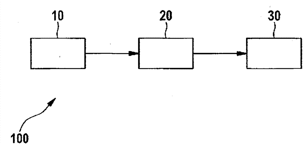
[0023] figure 1 A cooling ventilation device 100 is shown very simplified, which is usually installed in the engine compartment of a motor vehicle (not shown) and serves to cool the coolant of a combustion engine (not shown) of the motor vehicle. For this purpose, the cooling ventilation device 100 generates an air flow which flows through a cooler (not shown) and thereby cools the coolant within the cooler.

[0024] Cooling ventilation device 100 is actuated by a controller 10 , which can be designed, for example, as an electronic controller (ECU, electronic control unit). The controller 10 is electrically connected to a fan controller 20 (fan control module, FCM), which is used to control the electric fan motor 30 of the cooling ventilation device 100 connected to the fan controller 20 . For this purpose, the controller 10 supplies a pulse-width-modulated electrical signal to the fan controller 20 , which converts the signal into a corresponding voltage, thereby actuating t...


PUM


Abstract

A method for actuating an electric fan motor for an internal combustion engine of a motor vehicle, comprising the steps: - determining an operating duration during which the fan motor is operated below a rotational speed which is critical with regard to pasting; - wherein if the operating duration exceeds a duration which is critical with regard to pasting, the fan motor is operated for a defined time duration at a washing rotational speed which is higher than the rotational speed which is critical with regard to pasting.

Description

technical field [0001] The invention relates to a method for operating an electric fan motor for a combustion engine of a motor vehicle. Furthermore, the invention relates to a controller for carrying out such a method. Background technique [0002] Traditionally, motor cooling ventilation has been used for cooling functions within combustion engines of motor vehicles. In this case, the DC fan motor of the motor cooling fan usually has a vaned commutator, via which the rotor coil of the fan motor is energized by means of contact brushes. The rotational speed of the fan motor is usually predetermined by the electronic control unit (ECU, motor control unit) of the motor vehicle in order to ensure that the motor temperature is within an acceptable and safety-technically non-dangerous range. For example, the motor cooling fan can be used in such a way that its air flow cools a row of coolers arranged one behind the other in the motor compartment of the motor vehicle. [0003]...

Claims


Application Information

Patent Timeline
Patent Type & Authority Applications(China)
IPC IPC(8): F01P5/14F01P7/04
CPCF01P9/04F01P7/048F01P5/14
Inventor Y·穆热S·克鲁格
Owner ROBERT BOSCH GMBH
Why Eureka
Try Eureka