Electrophoretic display sheet and electrophoretic display medium using same
An electrophoretic display and electrophoresis technology, applied in identification devices, instruments, nonlinear optics, etc., can solve problems such as inability to seal electrophoretic fluids, sinking, etc., and achieve excellent productivity and low cost.
- Summary
- Abstract
- Description
- Claims
- Application Information
AI Technical Summary
Problems solved by technology
Method used
Image
Examples
no. 1 Embodiment approach 、 pic 1~ pic 9
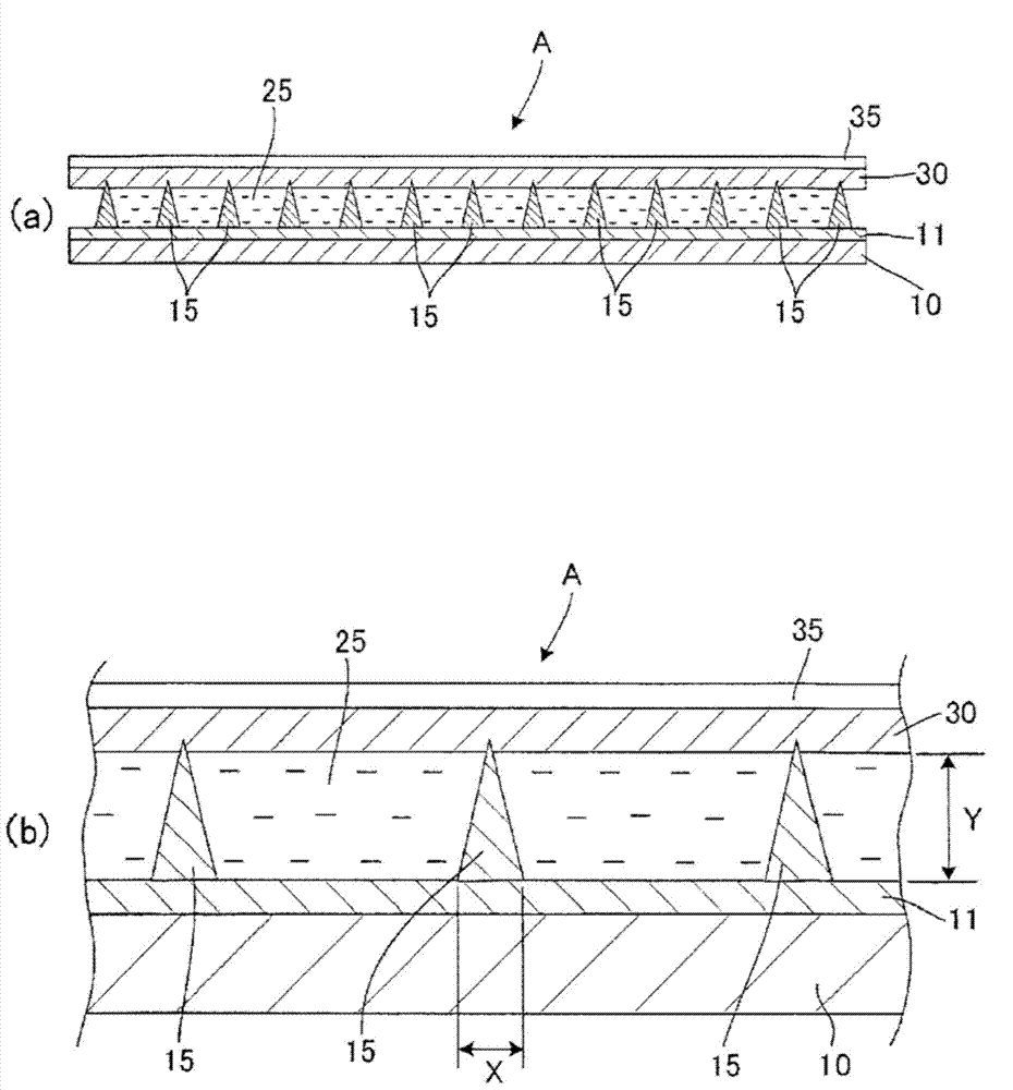
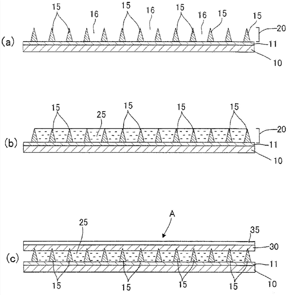
[0050] Figure 1 to Figure 9 It is explanatory drawing of 1st Embodiment which is an example of this invention, figure 1 It is a schematic longitudinal sectional view of the first embodiment and an enlarged schematic longitudinal sectional view thereof, figure 2 It is a schematic diagram illustrating the manufacturing process of the electrophoretic display panel according to the first embodiment step by step.
[0051] Such as figure 1 and figure 2 As shown, the electrophoretic display panel A constituting the first embodiment has: a translucent electrode surface 11 formed on a translucent substrate material 10; a honeycomb structure 20 formed on the translucent electrode surface 11 is composed of partition walls 15, 15... of insulating materials; electrophoretic ink (layer) 25, which is filled in the honeycomb structure 20; film 35, which is formed with a sealing adhesive layer (or sealing adhesive layer) 30 .
[0052] The translucent substrate material 10 may be any ...
no. 2 Embodiment approach 、 pic 10~ pic 1
[0095] (Second Embodiment, Figure 10 ~ Figure 12 )
[0096] Figure 10 ~ Figure 12 It is an explanatory diagram explaining the second embodiment of the present invention.
[0097] The electrophoretic display panel of the second embodiment is only different in the following construction method: instead of the film 35 formed with the sealing adhesive layer (or sealing adhesive layer) 30 used in the above-mentioned first embodiment, a After using the film 45 formed with the sealing precursor layer 40 to be attached to the electrophoretic ink layer 25, the sealing layer 41 is formed by curing the sealing precursor layer 40 to seal the electrophoretic ink layer 25, and then the film 45 is sealed from the sealing layer 41. peel off. Because the respective structures of substrate material 10, electrode surface 11, partition wall 15, honeycomb structure 20, electrophoretic ink (layer) 25 and Figure 3 ~ Figure 8 and its description (the structure in which the width of the short a...
no. 3 Embodiment approach 、 pic 13
[0117] (third embodiment, Figure 13 ~ Figure 15 )
[0118] Figure 13 ~ Figure 15 It is an explanatory drawing for explaining the third embodiment of the present invention.
[0119] The electrophoretic display panel of the third embodiment differs only in the following configuration method: instead of the film 35 formed with the sealing adhesive layer (or sealing adhesive layer) 30 used in the above-mentioned first embodiment and the above-mentioned first embodiment, the electrophoretic display panel is different. 2 The film 45 having the sealing precursor layer 40 used in the embodiment seals the electrophoretic ink by curing the adhesive layer 50 after bonding the sealing film 55 formed with the adhesive layer 50 to the electrophoretic ink layer 25. Layer 25. Because the respective structures of substrate material 10, electrode surface 11, partition wall 15, honeycomb structure 20, electrophoretic ink (layer) 25 and Figure 3 ~ Figure 8 and its description (the structur...
PUM
| Property | Measurement | Unit |
|---|---|---|
| Volume resistivity | aaaaa | aaaaa |
| Thickness | aaaaa | aaaaa |
| Thickness | aaaaa | aaaaa |
Abstract
Description
Claims
Application Information
 - R&D Engineer
- R&D Manager
- IP Professional
- Industry Leading Data Capabilities
- Powerful AI technology
- Patent DNA Extraction
Browse by: Latest US Patents, China's latest patents, Technical Efficacy Thesaurus, Application Domain, Technology Topic, Popular Technical Reports.
© 2024 PatSnap. All rights reserved.Legal|Privacy policy|Modern Slavery Act Transparency Statement|Sitemap|About US| Contact US: help@patsnap.com


