
Auxiliary power supply system of urban rail vehicle

A vehicle auxiliary and power supply system technology, applied to vehicle components, collectors, electric vehicles, etc., can solve the problems of large load starting current, heavy weight, and large power supply volume, and achieve the effect of reducing equipment cost and vehicle weight

Active Publication Date: 2014-04-16
青岛朗进集团有限公司
View PDF4 Cites 18 Cited by
  • Summary
  • Abstract
  • Description
  • Claims
  • Application Information

AI Technical Summary

Problems solved by technology

[0003] Because the output and input of the power supply need to be electrically isolated, the isolation transformer is large in size, heavy in weight, and low in efficiency, and the subsequent electrical equipment is an ordinary three-phase asynchronous motor or a high-power electric heater, such as an air conditioning unit, an air compressor, and a cooling fan. , electric heaters, etc., the load starting current is large, and the power supply needs to reserve a large power capacity to resist the load’s starting inrush current, which also causes the power supply to be bulky and heavy

Method used


Image

  • Auxiliary power supply system of urban rail vehicle
  • Auxiliary power supply system of urban rail vehicle
  • Auxiliary power supply system of urban rail vehicle

Examples


Embodiment 1

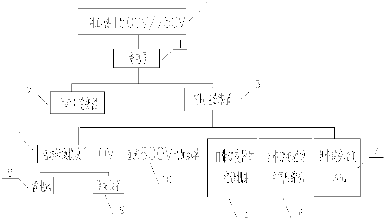
[0023] like figure 1 As shown, an auxiliary power supply system for urban rail vehicles according to the present invention includes a pantograph 1, a main traction inverter 2 and an auxiliary power supply device 3. The bow head of the pantograph 1 is in contact with the catenary 4, and the catenary The network voltage power supply of 4 is 1500V or 750V. After the current passes through the pantograph 1 and the main cable of the vehicle in sequence, the current is transmitted to the main traction inverter 2 and the auxiliary power supply device 3 .

[0024] Among them, the main traction inverter 2 converts the input 1500V or 750V direct current into three-phase alternating current and then outputs it to the traction motor connected thereto, so as to drive the traction motor and then drive the train.

[0025] The auxiliary power supply device 3 steps down the input DC power of 1500V or 750V, and then outputs a DC power supply of 400-750V. In this embodiment, the auxiliary power ...

Embodiment 2

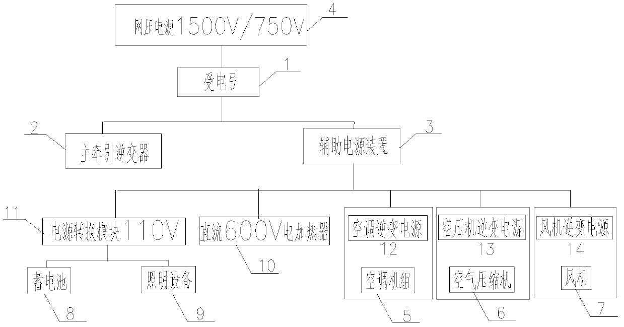
[0034] like figure 2 As shown, the difference from Embodiment 1 is that an air-conditioning inverter power supply 12 is connected at the input end of the air conditioning unit 5, an air compressor inverter power supply 13 is connected at the input end of the air compressor 6, and an air compressor inverter power supply 13 is connected at the input end of the air-conditioning unit 5. End is connected with a fan inverter power supply 14, the input end of the air conditioner inverter power supply 12, the air compressor inverter power supply 13 and the fan inverter power supply 14 is connected with the output end of the auxiliary power supply device 3, the air conditioner inverter power supply 12, the air compressor inverter power supply The inverter power supply 13 and the fan inverter power supply 14 are used to convert the 600V direct current output by the auxiliary power supply device 3 into 380V, 220V and other alternating currents required by the air conditioner unit 5, the ...

Embodiment 3

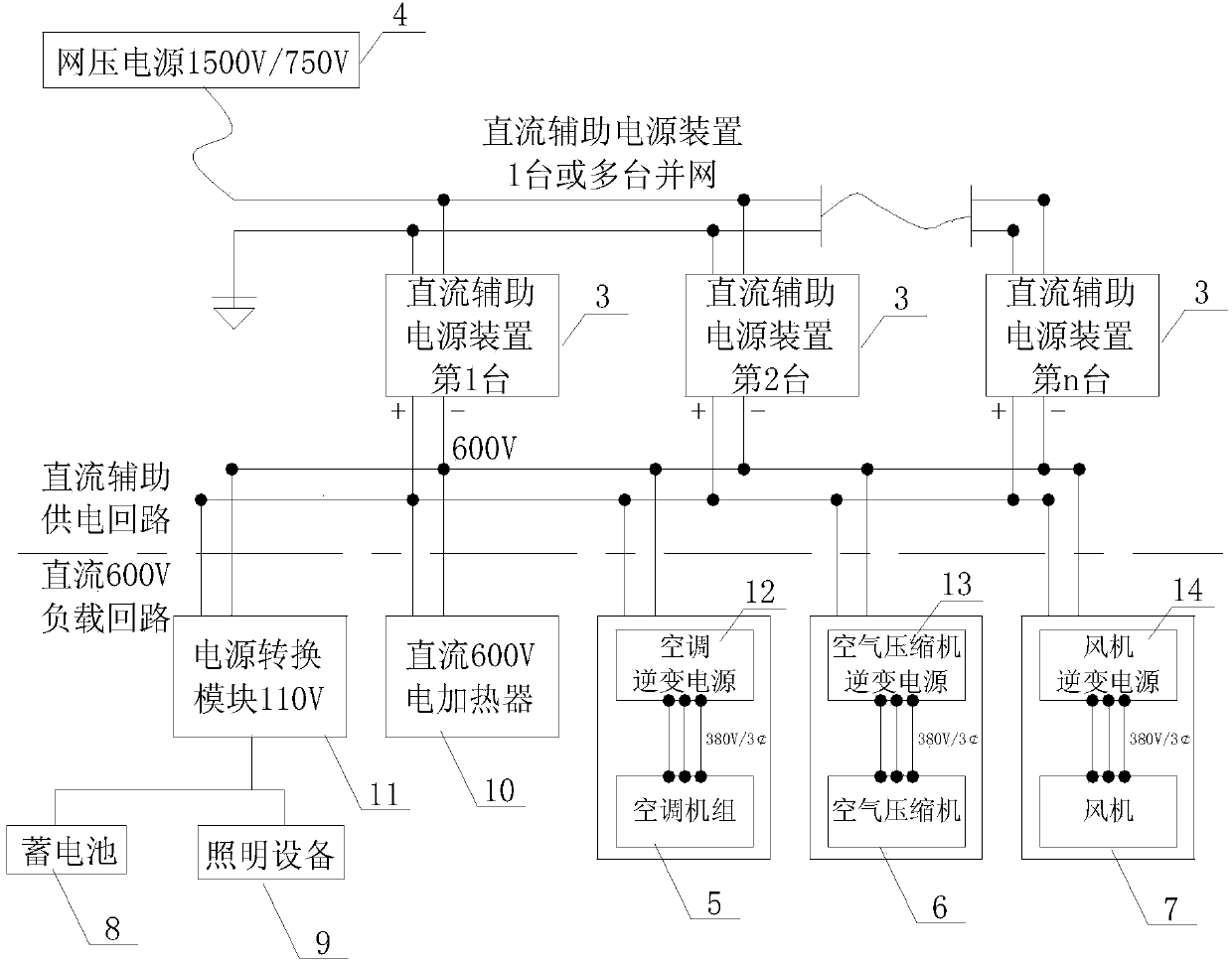
[0037] The difference from the above two embodiments is that in this embodiment, there are multiple auxiliary power supply devices 3, and the multiple auxiliary power supply devices 3 supply power to each electric load through DC grid connection, such as image 3 As shown, three auxiliary power supply devices 3 are used, which can not only ensure the power consumption of each load of the whole train, but also ensure that when one or two auxiliary power supply devices 3 fail, the other auxiliary power supply devices 3 can still guarantee required for train operation.


PUM


Abstract

The invention relates to an auxiliary power supply system of an urban rail vehicle. The auxiliary power supply system comprises a pantograph and a main traction inverter, and further comprises one or more auxiliary power supply devices. The pantograph transmits the current of a contact network to the main traction inverter and the auxiliary power supply devices. The auxiliary power supply devices output a direct-current power supply, and the output ends of the auxiliary power supply devices are connected with electricity loads. Some electricity loads are provided with inverters, or the input ends of some electricity loads are connected with an inverter power supply. The input ends of the inverters and the input end of the inverter power supply are connected with the output ends of the auxiliary power supply devices. According to the auxiliary power supply system of the urban rail vehicle, alternating current auxiliary power supplying of existing urban rail vehicles such as a metro and a light rail is converted into direct current auxiliary power supplying, and the direct current of an electric device is converted into the needed alternating current through the inverters or in the mode that the inverter power supply is connected to the input end of the electric device, so that the weight of the power supply device is greatly reduced, the whole vehicle weight is reduced, light weight of the metro and light rail vehicles is achieved, meanwhile, the device cost can be reduced, and the purposes of energy conservation and environment protection are achieved.

Description

technical field [0001] The invention relates to a power supply system installed on urban rail vehicles such as subways and light rails, and belongs to the technical field of urban rail vehicle power supply. Background technique [0002] At present, the auxiliary power supply system of urban rail transit vehicles such as subways and light rails in my country is to install one or more sets of auxiliary power supply (SIV), which inverts the catenary network voltage power supply from DC 1500V or 750V power supply to 380V 3 Phase 4-wire AC power supply, providing AC 3-phase 380V and AC single-phase 220V power for subsequent electrical equipment. [0003] Because the output and input of the power supply need to be electrically isolated, the isolation transformer is large in size, heavy in weight, and low in efficiency, and the subsequent electrical equipment is an ordinary three-phase asynchronous motor or a high-power electric heater, such as an air conditioning unit, an air compr...

Claims


Application Information

Patent Timeline
Patent Type & Authority Applications(China)
IPC IPC(8): B60L1/00
CPCY02T10/7241Y02T10/72
Inventor 李敬茂刘典马英华
Owner 青岛朗进集团有限公司
Learn More