
Device for achieving continuous supply of films automatically

A driving device and continuous film technology, applied in transportation and packaging, winding strips, thin material processing, etc., can solve the problems of waste materials, weak adhesion, unfavorable appearance, etc.

Inactive Publication Date: 2014-04-16
QUANZHOU KESHENG PACKAGING MACHINERY
View PDF8 Cites 2 Cited by
  • Summary
  • Abstract
  • Description
  • Claims
  • Application Information

AI Technical Summary

Problems solved by technology

[0002] At present, in packaging and other fields, the unwinding of packaging film is usually single-roll release. After the release is about to be completed, stop, cut, re-wind, and release again, and so on. This single-roll release cycle method not only requires Manual real-time attention also needs to judge whether the remaining amount can reach the amount of one packaging, if not, it needs to be cut, which is a waste of material, and once the judgment is inaccurate, the amount of packaging may not be enough, resulting in a failed packaging , need to rework
The existing method is not efficient, and personnel need to pay attention to the machine at all times, which also wastes materials.
There is another way to use a cutter to cut the packaging film, and then use double-layer adhesive tape to bond the front and rear two rolls of packaging film to form a continuous conveying state, but this cutting and bonding process is often prone to wrinkling. It is not conducive to the beauty of packaging, and the adhesion is not strong, and it is easy to wrinkle or the two layers of film are separated when there is tension during packaging.
The existing packaging film has a PE packaging film with a thickness of 0.3-1 mm. This film is not easy to be damaged when used for packaging and has a long service life. However, it is relatively difficult to cut this film, and the sharpness of the cutter is required High, when the cutter is used for a long time, it is easy to appear the phenomenon of continuous cutting

Method used


Image

  • Device for achieving continuous supply of films automatically
  • Device for achieving continuous supply of films automatically
  • Device for achieving continuous supply of films automatically

Examples


Embodiment Construction

[0020] The present invention will be further described in conjunction with the accompanying drawings and specific embodiments.

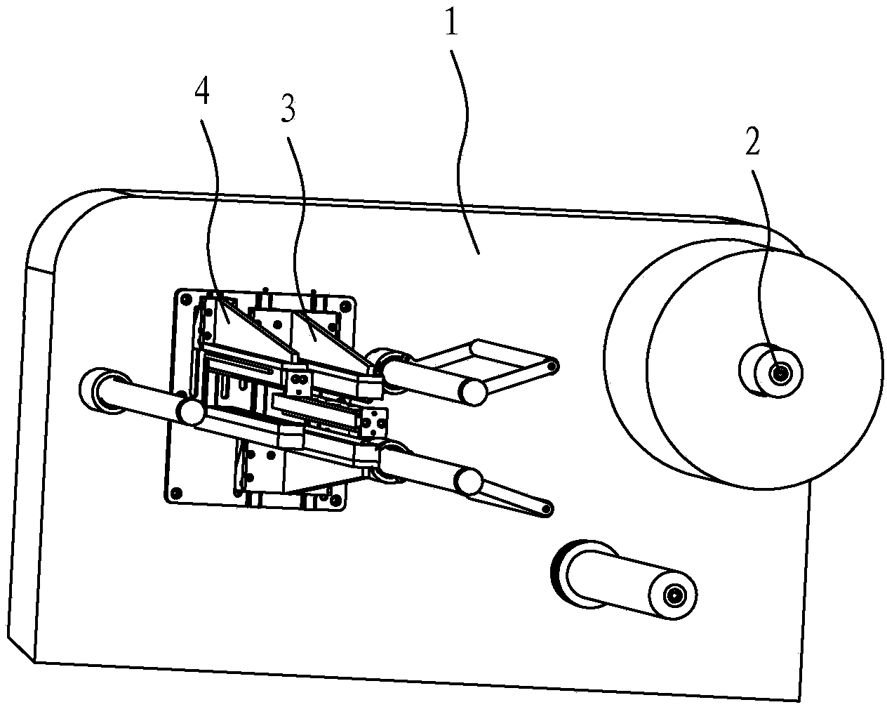
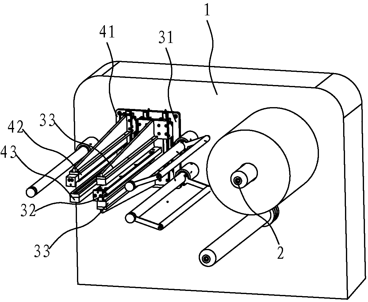
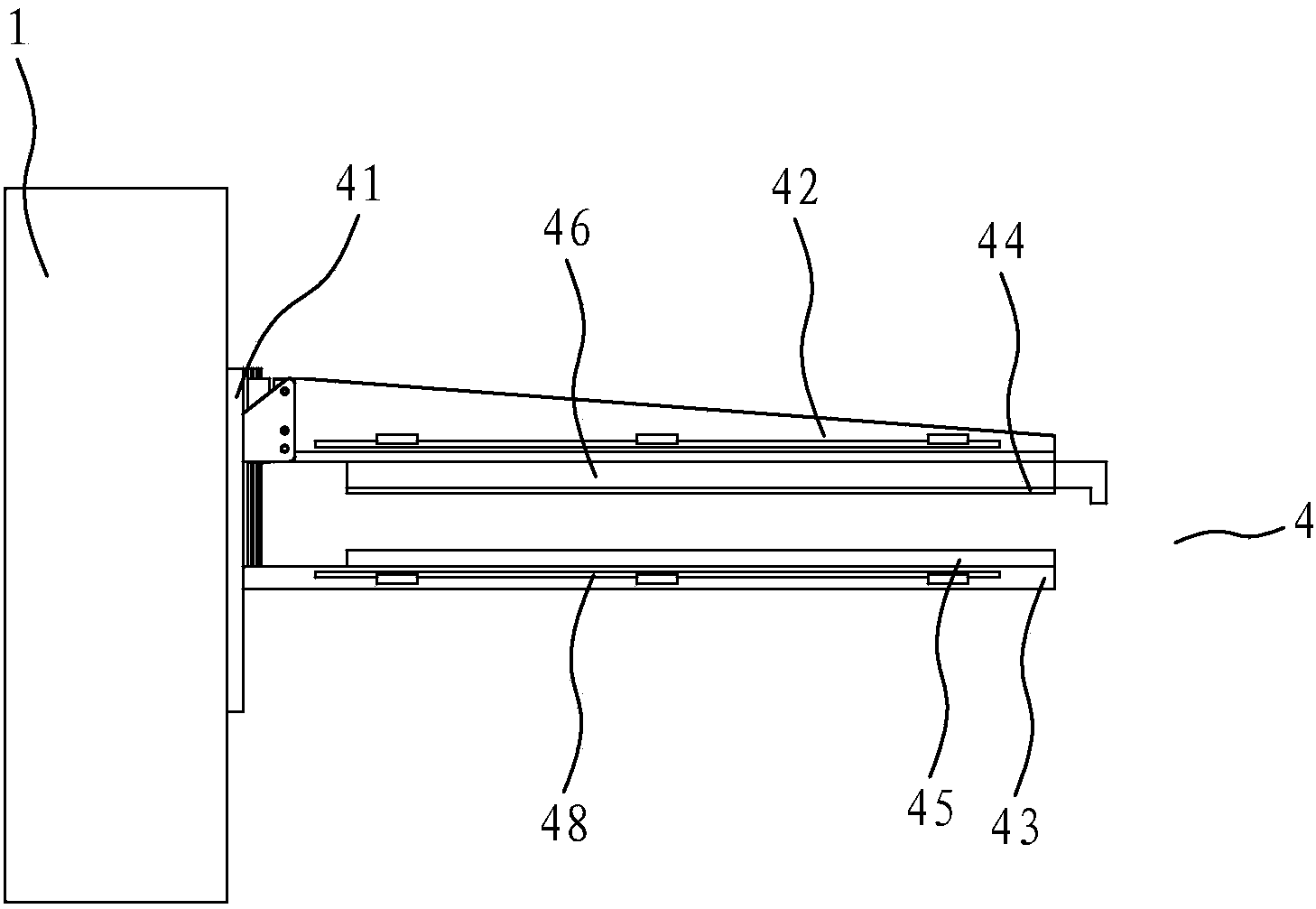
[0021] refer to Figure 1 to Figure 6 , the present embodiment provides an automatic film-continuing device, including a frame 1, two unwinding rollers 2 rotatably arranged on the frame, and a fusing device arranged in front of the unwinding roller 2 for cutting off the packaging film 3. A hot-melt bonding device 4 and an electrical control system arranged in front of the fusing device 3 for connecting two packaging films. Seat 32, the bracket 31 is located above and below the fuse seat 32 respectively with a press-fit seat 33, the two press-fit seats 33 can be driven by the drive device to move away from or close to the fuse seat 32, the fuse seat 32 The upper and lower sides are respectively provided with fuses 34 communicating with the external power supply, and the unwinding roller 2, the hot-melt bonding device 4, the fuses 34, and the fuse dri...


PUM


Abstract

The invention relates to a device for achieving continuous supply of films automatically. The device is simple in structure, high in working efficiency and capable of achieving automation film connection. The device comprises a machine frame, more than two unreeling rollers arranged on the machine frame in a rotary mode, a fusing device arranged in front of the unreeling rollers and used for cutting off the packaging films, a hot melting jointing device arranged in front of the fusing device and used for connecting two packaging films, and an electrical control system, wherein the fusing device comprises a support arranged on the machine frame, a fusing base arranged on the support, and a fusing driving device arranged on the support, two press-fit bases are arranged on the support and located above and below the fusing base respectively, the two press-fit bases can get away from or approach the fusing base under the driving of the fusing driving device, fusing wires communicated with an external power supply are arranged on the upper side and the lower side of the fusing base respectively, and the unreeling rollers, the hot melting jointing device, the fusing wires and the fusing driving device are all connected with the electrical control system.

Description

technical field [0001] The invention relates to an automatic film extension device. Background technique [0002] At present, in packaging and other fields, the unwinding of packaging film is usually single-roll release. After the release is about to be completed, stop, cut, re-wind, and release again, and so on. This single-roll release cycle method not only requires Manual real-time attention also needs to judge whether the remaining amount can reach the amount of one packaging, if not, it needs to be cut, which is a waste of material, and once the judgment is inaccurate, the amount of packaging may not be enough, resulting in a failed packaging , needs to be reworked. The existing method is not efficient, and personnel need to pay attention to the machine at all times, which also wastes materials. There is another way to use a cutter to cut the packaging film, and then use double-layer adhesive tape to bond the front and rear two rolls of packaging film to form a conti...

Claims


Application Information

Patent Timeline
IPC IPC(8): B65H19/20B65H19/18
Inventor 曾国耀
Owner QUANZHOU KESHENG PACKAGING MACHINERY
Learn More