Amplitude falling hydraulic system and engineering machinery

A hydraulic system and engineering machinery technology, applied in mechanical equipment, cranes, fluid pressure actuation devices, etc., can solve the problems of slow initial falling speed, affecting operation efficiency, difficulty in falling width control, etc., and achieve uniform and smooth falling process , Improve the safety and controllability, and the effect of smooth and vibration-free start-up

Inactive Publication Date: 2014-04-16
SANY AUTOMOBILE HOISTING MACHINERY
View PDF6 Cites 4 Cited by
  • Summary
  • Abstract
  • Description
  • Claims
  • Application Information

AI Technical Summary

Problems solved by technology

For the power drop control method, when the drop speed of the luffing cylinder changes greatly in a short period of time, it is easy to cause a large oscillation of the boom, which in turn causes a large fluctuation in the pressure of the rod chamber of the luffing cylinder , so that the jitter phenomenon occurs in the amplitude
[0005] In addition, the luffing angle of the boom can usually be changed between 0° and 75°. For the self-weight fall control method, when the fall is at a large angle, the initial fall speed is relatively slow, which is likely to affect the operating efficiency. The smaller the angle, the longer the arm length or the larger the load, the falling speed will become faster and faster, resulting in difficulty in controlling the fall and even posing safety hazards

Method used


Image

  • Amplitude falling hydraulic system and engineering machinery
  • Amplitude falling hydraulic system and engineering machinery
  • Amplitude falling hydraulic system and engineering machinery

Examples


Embodiment Construction

[0042] It should be pointed out that the description and sequence of specific structures in this section are only illustrations of specific embodiments, and should not be considered as limiting the protection scope of the present invention. In addition, the embodiments in this section and the features in the embodiments can be combined with each other under the condition of no conflict.

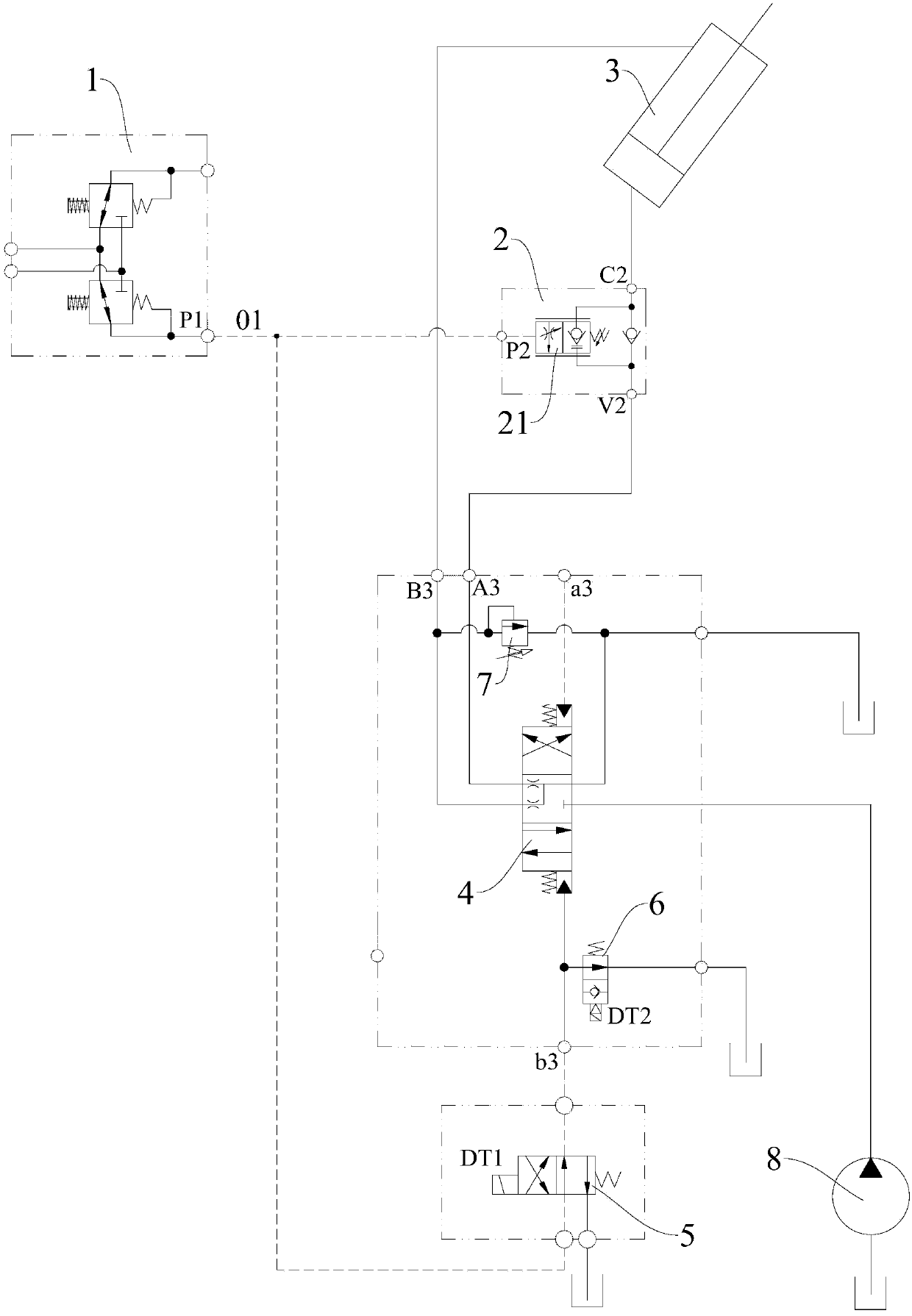
[0043] Please also refer to Figure 3 to Figure 6 , the embodiments of the present invention will be described in detail below in conjunction with the accompanying drawings.

[0044] combine image 3 As mentioned above, the hydraulic system of this embodiment may include a pilot handle valve 1, a luffing balance valve 2, an luffing cylinder 3, a main reversing valve 4, an anti-shock reversing valve 5, an oil pump 8 and an oil tank.

[0045] Wherein, the oil suction port of the oil pump 8 is connected to the oil tank, the oil inlet port of the main reversing valve 4 is connected to the oil o...


PUM


Abstract

The invention relates to the technical field of amplitude variation of engineering machinery and discloses an amplitude falling hydraulic system and the engineering machinery. The amplitude falling hydraulic system comprises an amplitude variation oil cylinder, a control oil path, a main reversing valve and an amplitude variation balance valve with a flow saturation characteristic, wherein a rod cavity and a rodless cavity of the amplitude variation oil cylinder are respectively connected to a first working oil opening of the main reversing valve and a free oil outlet of the amplitude variation balance valve; a second working oil opening of the main reversing valve is connected to a free oil inlet of the amplitude variation balance valve; the output end of the control oil path is connected to a control oil opening of the amplitude variation balance valve and an amplitude falling control oil opening of the main reversing valve. According to the amplitude falling hydraulic system and the engineering machinery, the amplitude falling starting speed in a large angle can be effectively increased; furthermore, control pressure of the amplitude variation balance valve comes from the control oil path and cannot be affected by a load, so that amplitude falling can be steadily started without shake; moreover, the amplitude variation balance valve has the flow saturation characteristic, so that the safety and the controllability of the amplitude falling operation can be effectively improved.

Description

technical field [0001] The invention relates to the technical field of luffing of engineering machinery, in particular to a hydraulic system of luffing amplitude and engineering machinery. Background technique [0002] At present, the fall control methods of wheeled cranes (such as truck cranes) mainly include power fall and self-weight fall. For a typical working principle of power drop see figure 1 As shown, among them, the left and right oil passages below the luffing balance valve 2' are respectively connected to the fall joint and the rise joint of the main reversing valve; in the process of falling, the output pressure of the fall joint of the main reversing valve oil, the rod chamber of the luffing cylinder 1' is pressurized, and the pressure also acts on the control oil port of the luffing balance valve 2', and then controls the luffing balance valve 2' together with the pressure of the rod chamber of the luffing cylinder 1' The opening of the balance spool 21' rea...

Claims


Application Information

Patent Timeline
IPC IPC(8): B66C23/82B66C13/20F15B11/08F15B13/044
Inventor 李小飞彭勇丁锋
Owner SANY AUTOMOBILE HOISTING MACHINERY
Why Eureka
Try Eureka