Electronic parts for high frequency power amplifier and wireless communication device

a technology of high-frequency power amplifiers and wireless communication devices, applied in the direction of gain control, instruments, transmission, etc., can solve the problem of not being able to avoid the occurrence of a response delay, the output power is raised to a desired level upon transmission start, and the controllability of low-output power is not satisfactory, so as to reduce detection sensitivity and enhance controllability. the effect of output power

Active Publication Date: 2007-03-22
RENESAS ELECTRONICS CORP +1
View PDF5 Cites 95 Cited by
  • Summary
  • Abstract
  • Description
  • Claims
  • Application Information

AI Technical Summary

Benefits of technology

[0023] Advantageous effects obtained by representative ones of the inventions disclosed in the present application will briefly be explained as follows:
[0024] High frequency power amplifying electronic parts (RF power module) can be realized which is capable of expanding a dynamic range of an output power detection circuit and obtaining a continuous detection output with no inflection point from a region low in power to a region high in ...

Problems solved by technology

A problem arises in that since the sensitivity of an output power detection circuit in a region low in output power is relatively low upon output power control for the conventional cellular phone, controllability of the output power at low output power is not satisfactory.
Therefore, it is not possible to avoid the occurrence of a response delay upon control loop switching.
As a result, there is a fear that a switching spectrum at so-called ramp-up that the output power ...

Method used


Image

  • Electronic parts for high frequency power amplifier and wireless communication device
  • Electronic parts for high frequency power amplifier and wireless communication device
  • Electronic parts for high frequency power amplifier and wireless communication device

Examples


first embodiment

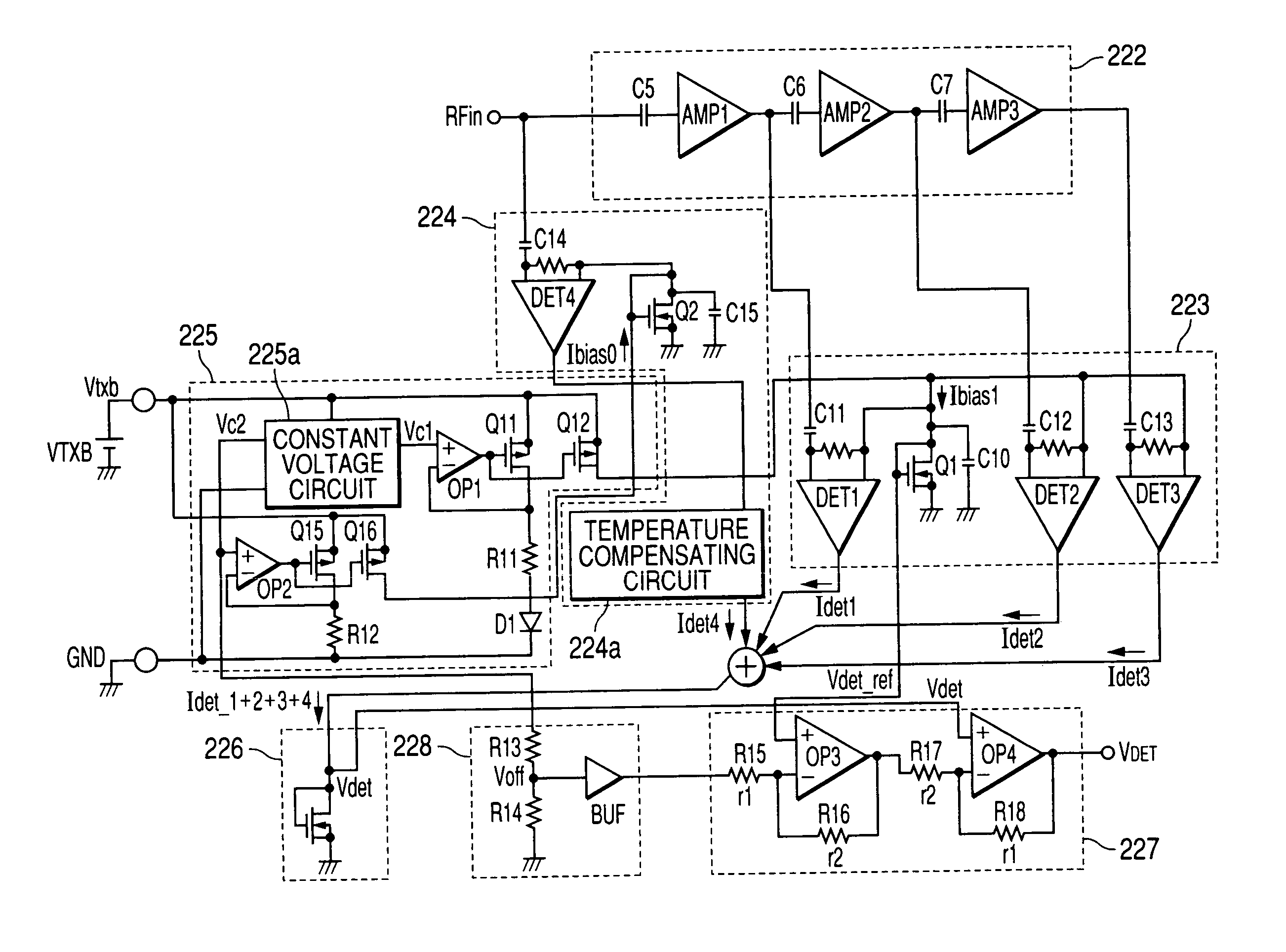
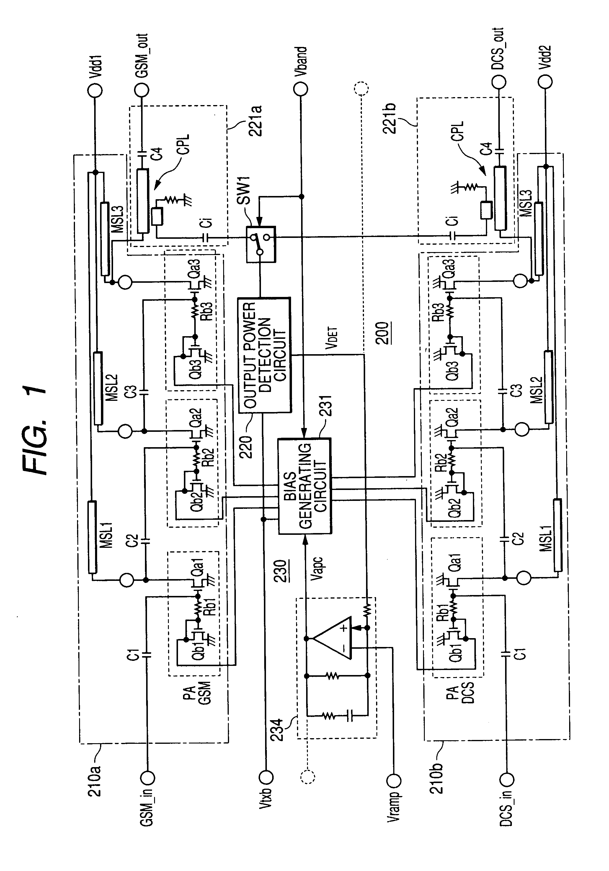
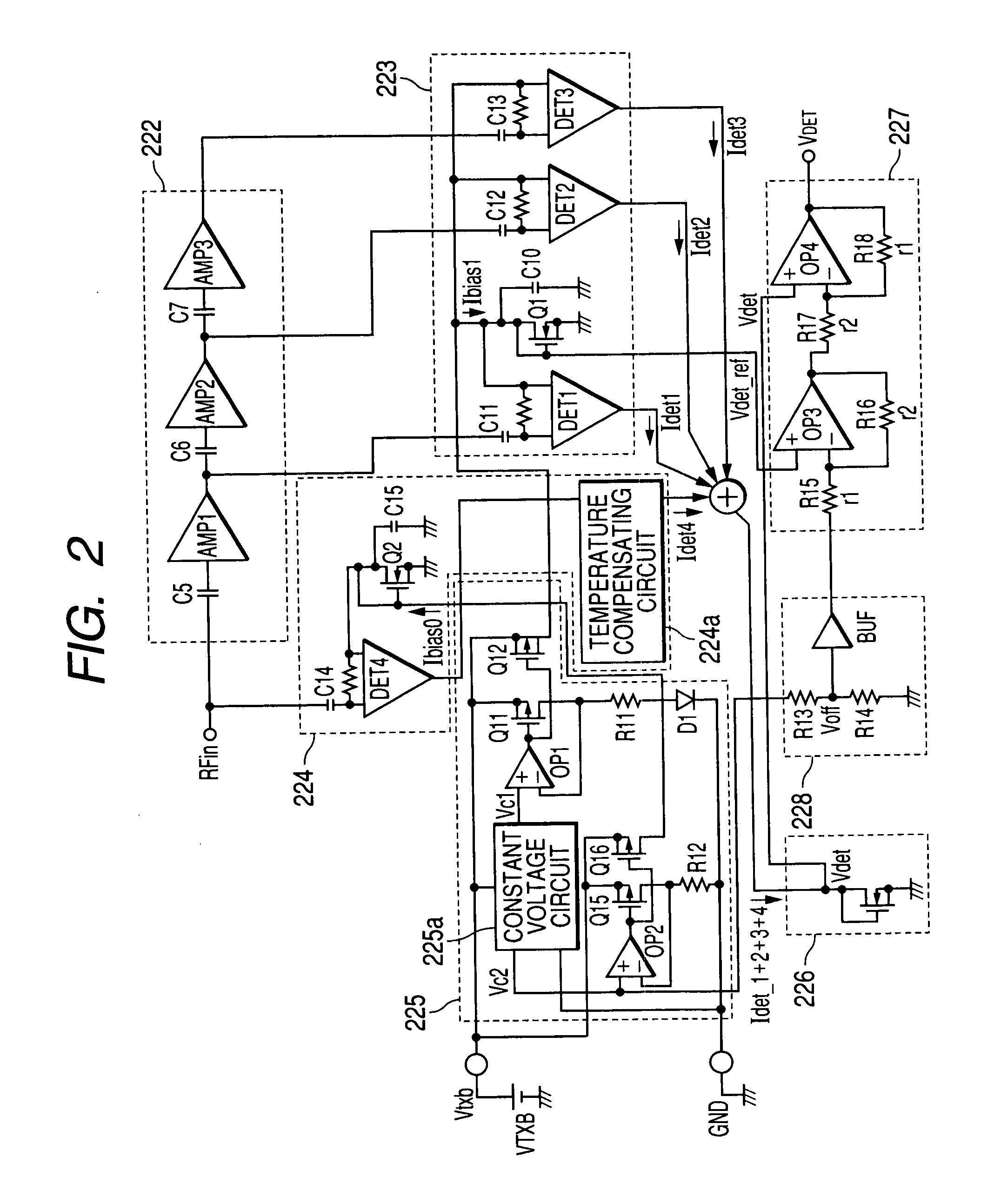
[0058] the output power detection circuit 220 is shown in FIG. 2. Incidentally, a signal indicated by a symbol RFin in FIG. 2 is a high frequency signal taken out from the output line of the high frequency power amplifier circuit 210a or 220b by the output extracting means 221a or 221b shown in FIG. 1. In FIG. 2, one (e.g., Q11) in which a symbol indicative of a MOSFET is marked with an outward arrow is a P channel MOSFET, whereas one (e.g., Q2) marked with an inward arrow is an N channel MOSFET (FIGS. 8 and 9 are similar thereto). Unless reference is made in particular, the transistor means MOSFET below.

[0059] The output power detection circuit 220 according to the present embodiment includes a multi-stage configured amplifier circuit 222 which amplifies the high frequency signal RFin extracted by the output extracting means 221a or 221b, a multi-detection circuit 223 which detects amplified signals of respective stages of the amplifier circuit 222, and a detection circuit 224 whic...

second embodiment

[0109] A schematic configuration of the output power detection circuit 220 is shown in FIG. 11. In FIG. 11, circuits identical to those shown in FIG. 2 and elements identical to those shown in FIG. 2 are given the same reference numerals, and their dual explanations are omitted.

[0110] As shown in FIG. 11, the output power detection circuit 220 according to the second embodiment has an attenuator 229 provided on the input side of a first detection circuit 224 which detects without through an amplifier circuit, a high frequency signal RFin taken out from the output of a high frequency power amplifier circuit 210 by a coupler 221 used as a directional power coupler (output extracting means). The second embodiment can be made identical in configuration to the first embodiment except for it.

[0111] The reason why the attenuator 229 is provided will be explained here. Assume that when the dynamic ranges of the first detection circuit 224 and the second detection circuit 223 are designed w...


PUM


Abstract

The present invention provides electronic parts for amplifying high frequency power capable of expanding a dynamic range of an output power detection circuit, obtaining a continuous detection output having no inflexion point from a low region of output power to its high region and thereby improving controllability of the output power. In a wireless communication system which controls output power of a high frequency power amplifier, based on an output power detection signal and a signal indicative of an output level, an output power detection circuit is provided with a multi-stage configured amplifier which amplifies a high frequency signal taken out via a coupler and capacitive elements. Further, a plurality of detection circuits which detect outputs of amplifiers of respective stages, and a detection circuit which detects the high frequency signal without passing through the multi-stage configured amplifier are provided. One obtained by combining the outputs of these detection circuits is inputted to an error amplifier for generating an output power control signal, as the output power detection signal to thereby generate a control signal for the high frequency power amplifier.

Description

CROSS-REFERENCE TO RELATED APPLICATION [0001] The present application claims priority from Japanese patent applications No. 2006-52115 filed on Feb. 28, 2006 and No. 2005-274822 filed on Sep. 22, 2005, the content of which is hereby incorporated by reference into this application. BACKGROUND OF THE INVENTION [0002] The present invention relates to a technique for expanding a dynamic range of an output detection circuit in high frequency power amplifying electronic parts (RF power module) with a high frequency power amplifier built therein and enhancing controllability of output power, and to a technique effective if applied to, for example, an RF power module used in a cellular phone and a wireless communication device using the same. An RF power module having built therein a high frequency power amplifier (PA) in which transistors such as MOSFETs (Metal Oxide Semiconductor Field-Effect-Transistor), GaAs-MESFETs, etc. is incorporated in a transmission output section of a wireless co...

Claims


Application Information

Patent Timeline
IPC IPC(8): H04B1/04H01Q11/12
CPCG01R21/01H03G3/3047H03G3/3042
Inventor TAKAHASHI, KYOICHIMATSUDAIRA, NOBUHIROYOKOI, TAKASHI
Owner RENESAS ELECTRONICS CORP
Why Eureka
Try Eureka