Turbocharger hysteresis compensation device based on air compensation of intake pipe

A technology of turbocharger and compensation device, which is applied in the direction of machines/engines, internal combustion piston engines, mechanical equipment, etc., and can solve problems such as insufficient power

Inactive Publication Date: 2014-04-16
HENAN INST OF ENG
View PDF5 Cites 3 Cited by
  • Summary
  • Abstract
  • Description
  • Claims
  • Application Information

AI Technical Summary

Problems solved by technology

[0005] This invention can effectively solve the problem of insufficient power in the initial stage of the vehicle, and even the vehicle can use a small displacement engine, avoiding the phenomenon of "big horse and small car" in which a large displacement engine is used in order to ensure the power performance in the initial stage

Method used


Image

  • Turbocharger hysteresis compensation device based on air compensation of intake pipe

Examples


Embodiment Construction

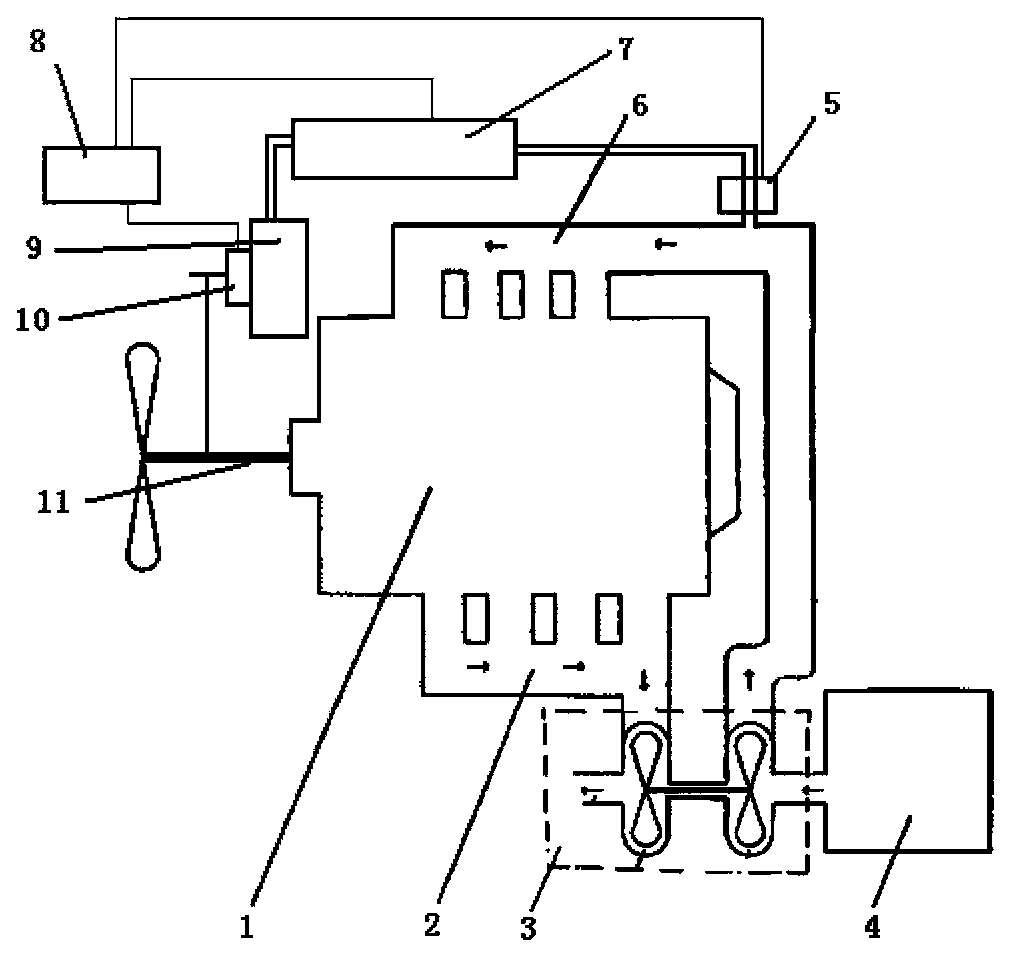
[0008] Such as figure 1 As shown, the turbocharger hysteresis compensation device based on intake pipe gas compensation provided by the present invention includes an engine 1, an exhaust pipe 2, a turbocharger 3, an air filter 4, a high-speed solenoid valve 5, and an intake pipe 6. Controller 8, output shaft 11, characterized in that: by adding an independent compressor 9 and an air storage tank 7 to the original engine system, the compressor 9 is connected to the output of the engine 1 through an electromagnetic clutch 10 The shaft 11 is connected, and the electromagnetic clutch 10 is controlled by the controller 8. When the pressure in the gas storage tank 7 is lower than the first set pressure, the controller 8 controls the electromagnetic clutch 10 to engage, so The air compressor 9 starts to work, and when the pressure in the air storage tank 7 reaches the second set pressure, the electromagnetic clutch 10 is controlled to disengage, and the air compressor 9 stops working...


PUM


Abstract

The invention relates to a turbocharger hysteresis compensation device based on air compensation of an intake pipe. An independent compressor and a gas storage tank are additionally arranged on an original engine system. The compressor is connected with an output shaft of an engine through an electromagnetic clutch which is controlled through a controller. When pressure in the gas storage tank is lower than first set pressure, the controller controls the electromagnetic clutch to combine, and the compressor starts to work. When the pressure in the gas storage tank reaches second set pressure, the electromagnetic clutch is controlled to separate, and the compressor stops working. When the rotating speed of the engine is low, a turbocharger does not work, and a high-speed solenoid valve is controlled by the controller to directly supply high-pressure air to the intake pipe of the engine.

Description

technical field [0001] The invention relates to a hysteresis compensation device for an engine turbocharger, in particular to a hysteresis compensation device for a turbocharger based on intake pipe gas compensation. Background technique [0002] Turbocharging uses the exhaust gas from the engine to drive the supercharger. The advantage is that the supercharging efficiency is higher than that of the mechanical supercharging. The disadvantage is that it is affected by the engine speed. The effect is not obvious at low speed. Performance. [0003] Boost lag is a major problem with turbocharged engines. At low speed, the turbocharger does not intervene, and the exhaust gas still drives the turbine to rotate, the exhaust is not as smooth as the naturally aspirated engine, and the torque output of the engine at this time is weaker than that of the naturally aspirated engine of the same displacement. As the speed of the engine increases, the turbocharger kicks in, and the power ...

Claims


Application Information

Patent Timeline
Patent Type & Authority Applications(China)
IPC IPC(8): F02B37/04F02B37/12
CPCY02T10/144Y02T10/12
Inventor 马宗正李振军李坤全杨安杰郭鹏马涛王献伟
Owner HENAN INST OF ENG
Why Eureka
Try Eureka