A fuel delivery high-pressure common rail system for jet thermal combustion

A technology of fuel delivery and common rail system, which is applied in charging systems, fuel injection devices, engine components, etc., can solve the problems of difficult pressure parameter detection points, no mechanical movement links, fluctuations in injection variables, etc., to improve safety and reliability. The effect of eliminating the principle defect and reducing the pulsation amplitude

Active Publication Date: 2016-03-16
BEIJING BDHLASER SCI & TECH
View PDF5 Cites 0 Cited by
  • Summary
  • Abstract
  • Description
  • Claims
  • Application Information

AI Technical Summary

Problems solved by technology

[0004] However, thermal combustion is different from power combustion. It is a direct conversion of chemical energy to thermal energy without mechanical movement. The form of energy conversion required is a continuous, stable, long-term combustion process. There are different requirements for the matching of nozzle diameters and injection variables; however, the existing mechanical direct-injection thermal combustion equipment has a simple structure. For thermal combustion, there are the following problems:
[0005] 1. The pressure energy pulsation of the delivered fuel will be directly transmitted to the nozzle, causing the injection variable (pressure, injection volume) to fluctuate, affecting the stability of combustion;
[0006] 2. At present, there is no technical basis for real-time continuous intelligent control, and it is difficult to set a suitable pressure parameter detection point on the entire conveying channel, so that stable, reliable and accurate control parameters cannot be obtained;
[0007] 3. The opening / closing of multi-stage fire control nozzles will generate a large pressure energy jump instantaneously, which makes the multi-nozzles crosstalk with each other
[0008] 4. It is difficult for a single delivery variable to adapt to the adaptability of nozzles of different calibers during multi-stage fire control

Method used


Image

  • A fuel delivery high-pressure common rail system for jet thermal combustion
  • A fuel delivery high-pressure common rail system for jet thermal combustion
  • A fuel delivery high-pressure common rail system for jet thermal combustion

Examples


Embodiment Construction

[0027] The following examples provided by the present invention are only for further illustrating the application of the present invention, rather than limiting.

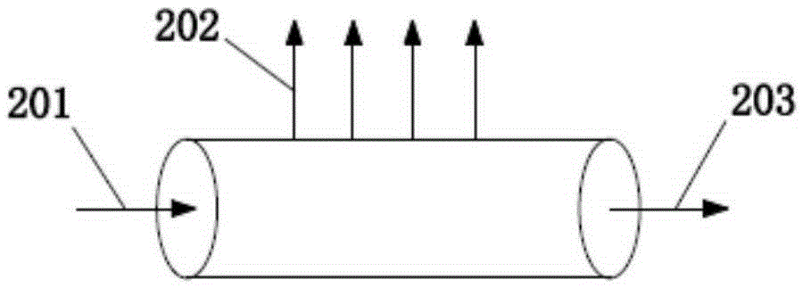
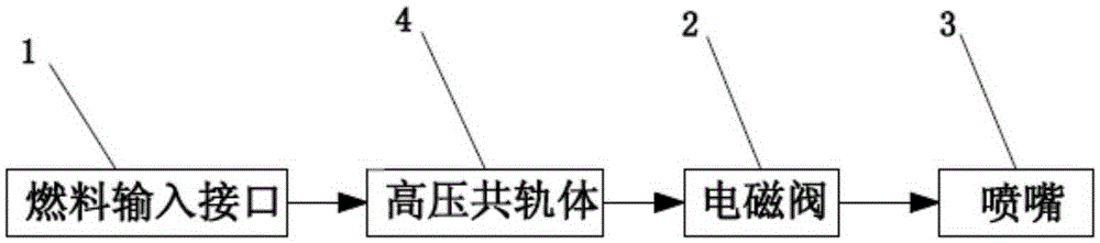
[0028] Such as figure 2 As shown, a fuel delivery high-pressure common rail system for injection thermal combustion, the common rail system includes a fuel input interface 1, a high-pressure common rail body 4, a solenoid valve 2 and a nozzle 3 connected in sequence through a fuel delivery pipe, The fuel input interface 1 can be a pump pressure delivery interface, a pneumatic medium delivery interface or a pipeline booster delivery interface, and the high-pressure common rail body 4 can be provided with multiple fuel inlets and outlets, and the multiple outlets are correspondingly provided with multiple groups of electromagnetic Valve 2 and nozzle 3, one solenoid valve 2 can be connected to one nozzle 3 correspondingly, and can also be connected to multiple nozzles 3 at the same time, part or all of the fuel outlet...


PUM


Abstract

The invention discloses a fuel-conveying high-pressure common rail system for spraying thermal combustion. The common rail system comprises a fuel input connector, a high-pressure common rail body, an electromagnetic valve and a nozzle, which are successively connected with one another through a fuel-conveying pipe, wherein the high-pressure common rail body is internally provided with a fuel storing cavity body with a fuel inlet and a fuel outlet, an output connector and a conveying variable regulating device; the storing cavity body is internally provided with damping walls which are arranged by being perpendicular to or inclined relative to the fuel flow feeding direction and form fuel-conveying channels, and the fuel-conveying channels of the adjacent damping walls are positioned on different axes; the output connector has the function of avoiding mutual disturbance, and the conveying variable regulating device can regulate multiple output conveying variables. The high-pressure common rail system provided by the invention has the advantages that the pressure energy in a fuel conveying process is stored, the pressure fluctuation is smoothed, and multiple conveying variables are output to guarantee the continuity, stability and accurate controllability of the spraying combustion.

Description

technical field [0001] The invention relates to a thermal combustion fuel (liquid, gas fuel) delivery system, in particular to a fuel delivery high-pressure common rail system for injection thermal combustion. Background technique [0002] The existing high-power thermal combustion equipment, whether using traditional fuels such as fuel oil, natural gas, or liquefied petroleum gas, or using new clean fuels such as alcohol-based industrial gases and liquid fuels, generally adopts simple mechanical direct injection technology, which can only Realize basic extensive combustion; however, with the continuous improvement of power combustion emission standards, gasoline and diesel engines have generally realized "electric injection", and the core of its technology is high-pressure common rail technology. A high-pressure common rail technology and device suitable for jetting thermal combustion fuel (liquid, gaseous fuel) delivery, enabling thermal combustion technology to realize th...

Claims


Application Information

Patent Timeline
Patent Type & Authority Patents(China)
IPC IPC(8): F02M55/02
Inventor 张志远邬江兴王伟平张宁邬东建王蓓
Owner BEIJING BDHLASER SCI & TECH
Why Eureka
Try Eureka