
Solar cell

A solar cell and photoelectric conversion technology, applied in the field of solar cells, can solve problems such as low conversion efficiency of solar cells

Inactive Publication Date: 2014-04-16
AU OPTRONICS CORP
View PDF4 Cites 3 Cited by
  • Summary
  • Abstract
  • Description
  • Claims
  • Application Information

AI Technical Summary

Problems solved by technology

[0004] The invention proposes a solar cell to solve the problem of low conversion efficiency of existing solar cells

Method used


Image

  • Solar cell
  • Solar cell
  • Solar cell

Examples


Embodiment Construction

[0028] A number of embodiments of the present invention will be disclosed in the following figures. For the sake of clarity, many practical details will be described together in the following description. It should be understood, however, that these practical details should not be used to limit the invention. That is, in some embodiments of the present invention, these practical details are unnecessary. In addition, for the sake of simplifying the drawings, some existing conventional structures and elements will be shown in a simple and schematic manner in the drawings.

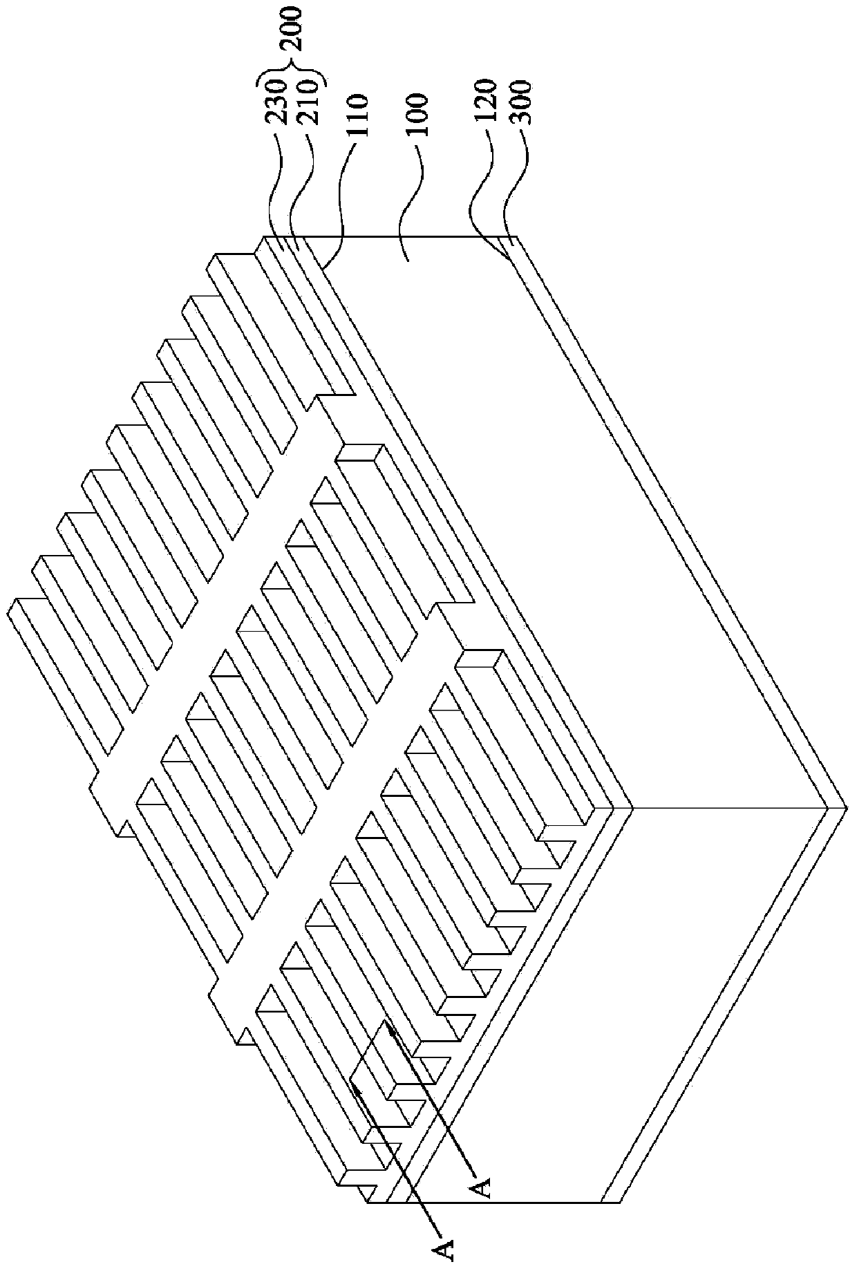
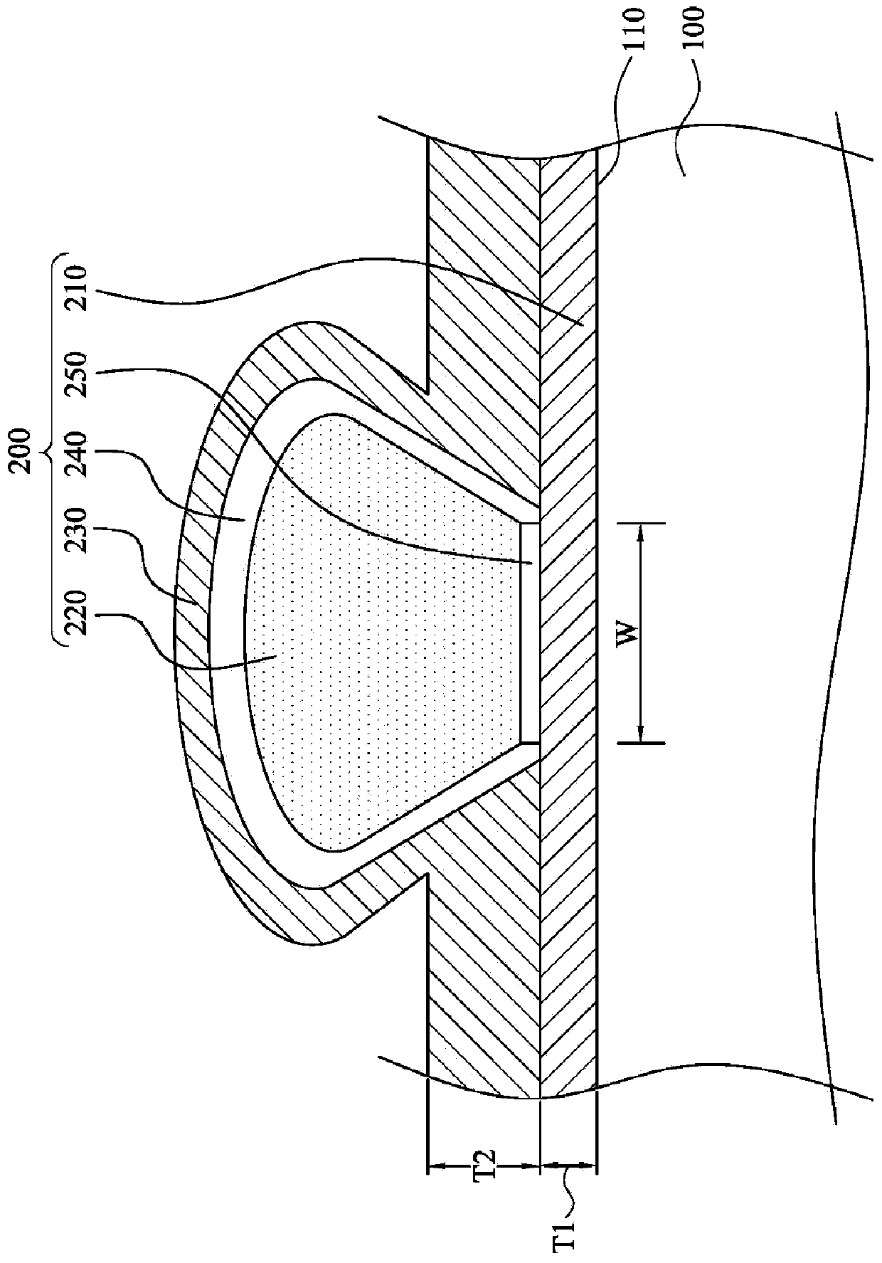
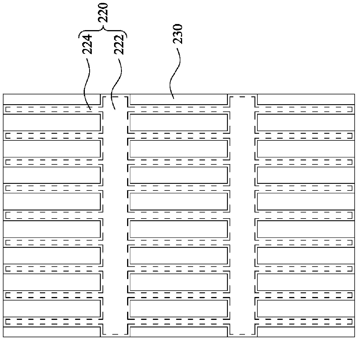
[0029] Please also refer to figure 1 and figure 2 ,in figure 1 is a perspective view of a solar cell according to an embodiment of the present invention, and figure 2 for along figure 1 A cross-sectional view of an embodiment of the line segment A-A. As shown in the figure, the solar cell includes a photoelectric conversion structure 100 , a first conductive structure 200 and a second conductive struc...


PUM


Abstract

The invention discloses a solar cell which comprises a photovoltaic conversion structure, a first electricity conduction structure and a second electricity conduction structure. The photovoltaic conversion structure is provided with a light inlet face and a back face opposite to the light inlet face. The first electricity conduction structure is arranged on the light inlet face of the photovoltaic conversion structure and electrically connected with the photovoltaic conversion structure. The first electricity conduction structure comprises a first transparent electricity conduction layer, an electrode structure and a second transparent electricity conduction layer. The first transparent electricity conduction layer is arranged on the light inlet face of the photovoltaic conversion structure. At least part of the first transparent electricity conduction layer is arranged between the electrode structure and the light inlet face of the photovoltaic conversion structure. The second transparent electricity conduction layer covers the electrode structure and the first transparent electricity conduction layer. The second electricity conduction structure is arranged on the back face of the photovoltaic conversion structure.

Description

technical field [0001] The invention relates to a solar cell. Background technique [0002] Reducing the size of metal electrodes of solar cells is currently one of the major trends in solar cell technology. Small-sized metal electrodes can reduce the area covered by the metal electrodes on the photoelectric conversion structure, thereby increasing the light collection efficiency of the solar cell. However, once the metal electrodes shrink, the resistance of the solar cell itself will increase, which in turn will reduce the efficiency of the solar cell. [0003] On the other hand, although metal electrodes made by copper electroplating can achieve smaller-sized metal electrodes, due to the characteristics of the electroplating process, the cross-section of the metal electrodes formed is mostly mushroom-shaped, which will increase the coverage of the metal electrodes on the photoelectric conversion structure. and reduce the contact area between the electrode and the transpa...

Claims


Application Information

Patent Timeline
Patent Type & Authority Applications(China)
IPC IPC(8): H01L31/0224H01L31/04
CPCY02E10/50H01L31/022425H01L31/022475H01L31/02168H01L31/022466H01L31/0547Y02E10/52
Inventor 简怡峻张杰
Owner AU OPTRONICS CORP
Learn More