Precision forming method and device for flat gear with flange
A precision forming and gear technology, applied in forging/pressing/hammer devices, wheels, transportation and packaging, etc., can solve the problems of increased extrusion force and insufficient filling of gear teeth, so as to control the cost of a single piece and ensure the life of the mold , The effect of eliminating the cutting process
- Summary
- Abstract
- Description
- Claims
- Application Information
AI Technical Summary
Problems solved by technology
Method used
Image
Examples
Embodiment 1
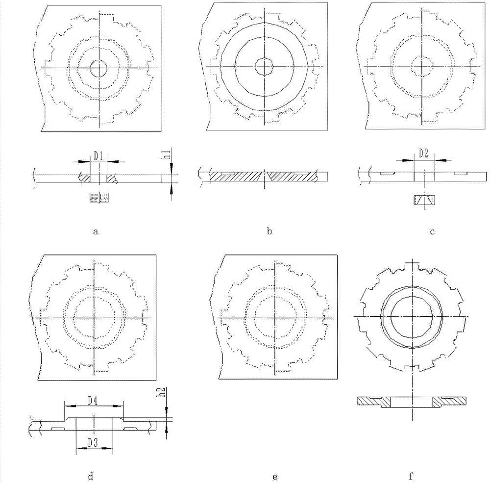
[0029] like figure 1 As shown, this embodiment includes the following steps:
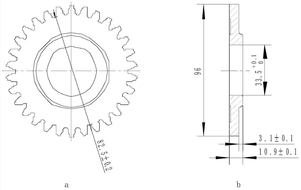
[0030] The first step, blank preparation, using strips, such as image 3 As shown in the figure, the thickness of the blank is taken as the thickness of the involute gear teeth, and the width of the blank is 1.2 times the diameter of the tip circle; the strip used needs to be spheroidized and annealed, and the spheroidization rate is greater than or equal to 85%.
[0031] The second step is to punch the center hole, which is a process auxiliary hole and plays the role of a shunt hole in the next forming process. Compared with the pre-punched hole, the diameter of the central hole is reduced by 1.0 mm on one side.
[0032] The third step is to extrude the annular groove to form the upper flange, and obtain the annular groove through extrusion deformation. During the extrusion process, the excess metal flows radially inward into the central hole, and the annular groove naturally forms the upper flan...
Embodiment 2
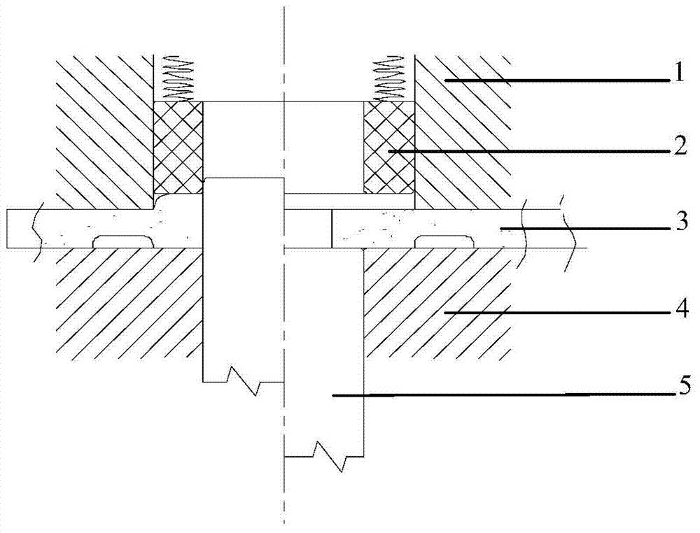
[0038] like figure 2 As shown, applied to the device of Embodiment 1, the device is a composite mold for flanging and upsetting, including: an upper mold, a lower mold, an upper concave mold and a lower punch, wherein: the upper mold moves downward first, and the The lower die jointly presses the blank and applies a pressure of 15MPa, the lower punch moves upwards to form flanging, and then the floating-controlled upper die moves downwards to upsetting to the target height of the lower flange of the gear to be fabricated.
[0039] The floating control refers to using an independent hydraulic pump to control the upward or downward movement of the upper die.
[0040] The upper die is a simple ring structure, which is convenient for its processing and manufacture, and is driven by a floating control unit.
Embodiment 3
[0042] This embodiment includes the following steps:
[0043] The first step, blank preparation, using strips, such as Figure 4 As shown in the figure, the thickness of the blank is taken as the thickness of the teeth of the rectangular gear, and the width of the blank is 1.1 times the diameter of the tip circle.
[0044] The second step is to punch the center hole, which is a process auxiliary hole and plays the role of a shunt hole in the next forming process. Compared with the pre-punched hole, the diameter of the central hole is reduced by 1.5mm on one side.
[0045] The third step is to extrude the annular groove to form the upper flange, and obtain the annular groove through extrusion deformation. During the extrusion process, the excess metal flows radially inward into the central hole, and the annular groove naturally forms the upper flange of the gear part after extrusion. .
[0046] The fourth step is to punch the central waste hole, punch out the waste formed by...
PUM
| Property | Measurement | Unit |
|---|---|---|
| spheroidization rate | aaaaa | aaaaa |
Abstract
Description
Claims
Application Information
 - R&D
- Intellectual Property
- Life Sciences
- Materials
- Tech Scout
- Unparalleled Data Quality
- Higher Quality Content
- 60% Fewer Hallucinations
Browse by: Latest US Patents, China's latest patents, Technical Efficacy Thesaurus, Application Domain, Technology Topic, Popular Technical Reports.
© 2025 PatSnap. All rights reserved.Legal|Privacy policy|Modern Slavery Act Transparency Statement|Sitemap|About US| Contact US: help@patsnap.com


