Blast furnace coal injection combustion improver as well as application and device thereof

A technology of blast furnace coal injection and combustion accelerant, which is applied in the field of iron and steel metallurgy, can solve the problems of large amount of catalyst addition, corrosion and shortage of blast furnace equipment and gas pipelines, etc., to improve the quality and output of molten iron, increase the production capacity of the blast furnace, and achieve huge economic benefits Effect

Active Publication Date: 2015-07-15
MCC CAPITAL ENGINEERING & RESEARCH +1
View PDF5 Cites 2 Cited by
  • Summary
  • Abstract
  • Description
  • Claims
  • Application Information

AI Technical Summary

Problems solved by technology

These substances will play a certain role in strengthening coal combustion, but due to the lack of understanding of blast furnace coal injection catalytic combustion, various methods often have problems such as large amount of catalyst addition and high cost, and the actual industrial use effect is not obvious.
A small number of solid catalytic combustion aids (such as chloride salts, nitrates or sodium and potassium salts, etc.) can significantly reduce the amount of combustion aids added, but they have a corrosive effect on blast furnace equipment and gas pipelines, and even have adverse effects on the blast furnace.
[0004] On the whole, the main problems of blast furnace coal-injection combustion-supporting technology are as follows: (1) The main function of pulverized coal combustion-supporting agent is to reduce the ignition point of coal powder and improve combustion efficiency. The number of combustion aid particles is the key to solve the problem of catalyst nanoparticle technology and coal powder adhesion and dispersion technology; (2) Since coal dust combustion aid is a one-time consumption catalyst, it is necessary to reduce the amount of combustion aid for large-scale industrial application. Preparation cost and consumption; (3) The composition and ratio of the pulverized coal combustion enhancer are related to the coal type, and the combustion enhancer needs to be dedicated to coal in order to exert a greater combustion-supporting effect; (4) The high-efficiency effect of the combustion enhancer depends on The design of the combustion-supporting system and excellent equipment are the guarantee for the high-efficiency performance of the blast furnace coal injection combustion-supporting technology. If the addition method is not appropriate, the combustion-supporting and energy-saving effect will also be lost

Method used


Image

  • Blast furnace coal injection combustion improver as well as application and device thereof
  • Blast furnace coal injection combustion improver as well as application and device thereof
  • Blast furnace coal injection combustion improver as well as application and device thereof

Examples


Embodiment 1

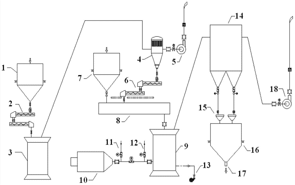
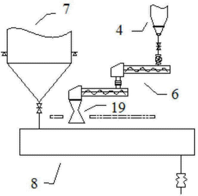
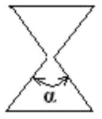
[0059] A blast furnace coal injection device, such as Figure 1-3 Shown: combustion aid raw material bin 1, screw feeder 2, ultrafine mill 3, combustion aid storage tank 4, combustion aid storage tank 4 is equipped with a second exhaust fan 5, screw metering pump 6, raw coal bunker 7, airtight Weighing coal feeder 8, coal mill 9, powder collector 14, sawdust separator 15 and coal powder bin 16, a Laval pipe 19 is set at the outlet end of the screw metering pump, and a sealed fan 13 is set on the coal mill 9, and The first exhaust fan 18 is set on the powder collector 14, the heating furnace 10 is set on the coal mill 9, the coal grinding machine 9 is connected with the heating furnace 10 through a pipeline, and the release valve 11 and the cold air valve 12 are arranged in sequence on the pipeline; The diffraction angle α of the Val tube is 62°; the distance between the center line of the Laval tube 19 and the edge of the raw coal bunker 7 is 22 cm, and the Laval tube 19 is ar...

Embodiment 2

[0062] The blast furnace coal injection device is the same as that in Example 1, except that the diffraction angle α of the Laval tube is 52°; the distance between the center line of the Laval tube 19 and the edge of the raw coal bunker 7 is 31 cm.

Embodiment 3

[0064] The blast furnace coal injection device is the same as that of Example 1, except that the diffraction angle α of the Laval tube is 46°; the distance between the center line of the Laval tube 19 and the edge of the raw coal bunker 7 is 46 cm.

[0065] Method Example 1

[0066] Using a steel plant 500m 3 Coal-injection combustion-supporting test was carried out in blast furnace, and the energy-saving effect of combustion-supporting agent on blast furnace coal-injection combustion-supporting was investigated with 15 days as a test period. The type of coal injected is anthracite. The equipment is the blast furnace coal injection device of equipment embodiment 1.

[0067] In the first phase of the test, about 10% of blast furnace dust, about 10% of mine ash, about 20% of dolomite, about 20% of converter dust, and about 40% of limestone were used as the combustion improver in the first phase of the test. The comprehensive composition is: CaO about 10%, MgO about 10%, CaCO ...


PUM

PropertyMeasurementUnit
diameteraaaaaaaaaa
combustion efficiencyaaaaaaaaaa

Abstract

The invention provides a blast furnace coal injection combustion improver as well as an application and a device thereof, which is applicable to the field of blast furnace coal injection combustion. Metallurgy ore and waste steel such as limestone, dolomite, blast furnace dust, sintering dust and converter dust, are used as raw materials and are remachined into a coal powder combustion improver after component optimization, wherein the combustion improver is mainly prepared from the following components in percentage by weight: 5-15% of blast furnace dust, 10-20% of bunker ash, 10-25% of dolomite, 30-50% of converter dust and 20-40% of limestone; subsequently the mixed raw materials are fed into a coal grinding machine through a combustion improver preparation and feeding system, coal powder surface modification is accomplished in the coal powder preparation process, and the purposes that the ignition point of the coal powder is reduced, the combustion efficiency of the coal powder before a blast furnace air inlet is accelerated, the coal-furnace ratio and the coke ratio are improved, and the comprehensive economic benefits in blast furnace coil injection are improved, are finally achieved.

Description

technical field [0001] The invention belongs to the iron and steel metallurgy industry, and in particular relates to a blast furnace coal injection combustion aid and its application and device. Background technique [0002] From the perspective of the traditional steel production process, the ironmaking system is one of the main energy-consuming processes, accounting for about 70% of the total energy consumption of steel production. In order to reduce ironmaking energy consumption, reduce pollution emissions and improve economic benefits, pulverized coal injection technology is widely used in blast furnace ironmaking at home and abroad to reduce coke consumption. However, a large number of theoretical studies and practices have shown that the combustion rate of pulverized coal in the tuyere area is less than 70%. As the amount of coal injection increases, the combustion rate of pulverized coal in the tuyere swirl area will gradually decrease. The remaining unburned pulveri...

Claims


Application Information

Patent Timeline
Patent Type & Authority Patents(China)
IPC IPC(8): C10L9/10C21B5/00
Inventor 赵志龙王艳民全强张波施设
Owner MCC CAPITAL ENGINEERING & RESEARCH
Why Eureka
Try Eureka