
Connecting rod piston type combustion chamber combined dead-center-free reciprocating internal combustion engine

A combustion chamber and piston-type technology, which is applied to combustion engines, pistons, mechanical equipment, etc., can solve problems such as shortening the service life of internal combustion engines, pistons being unable to transmit thrust, and increasing crankshaft load, so as to improve work efficiency, power performance and economy Sex, the effect of increasing the thrust area

Inactive Publication Date: 2014-04-23
尹建
View PDF6 Cites 5 Cited by
  • Summary
  • Abstract
  • Description
  • Claims
  • Application Information

AI Technical Summary

Problems solved by technology

The main reason is that the thrust direction of the traditional internal combustion engine piston can only be the downward direction of the piston, that is, the piston cannot transmit thrust in multiple directions
When the piston reaches the top dead center, the thrust will not only do no work but also directly act on the crankshaft, increasing the load on the crankshaft and causing varying degrees of damage to the crankshaft and the entire internal combustion engine, thereby shortening the service life of the internal combustion engine

Method used


Image

  • Connecting rod piston type combustion chamber combined dead-center-free reciprocating internal combustion engine
  • Connecting rod piston type combustion chamber combined dead-center-free reciprocating internal combustion engine
  • Connecting rod piston type combustion chamber combined dead-center-free reciprocating internal combustion engine

Examples


Embodiment Construction

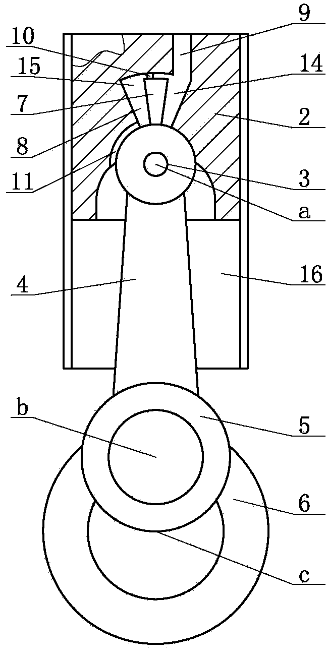
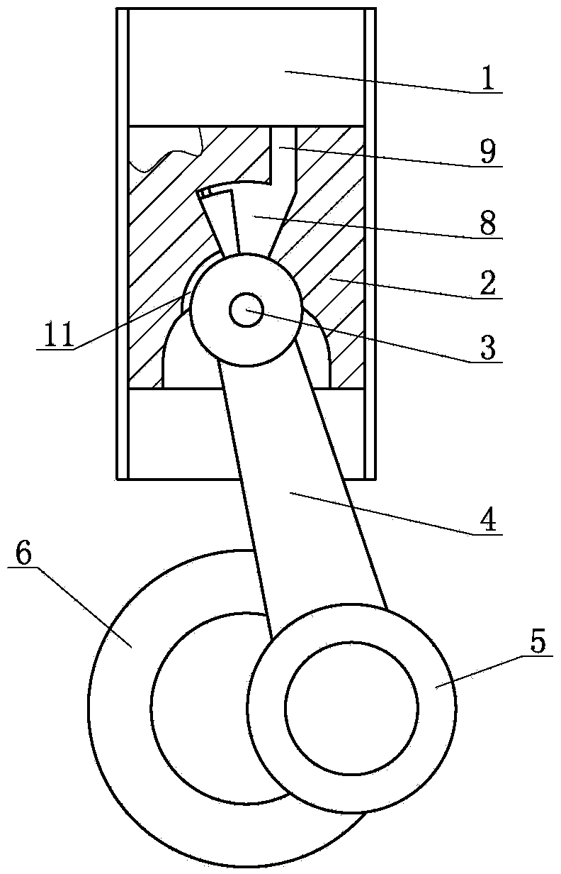
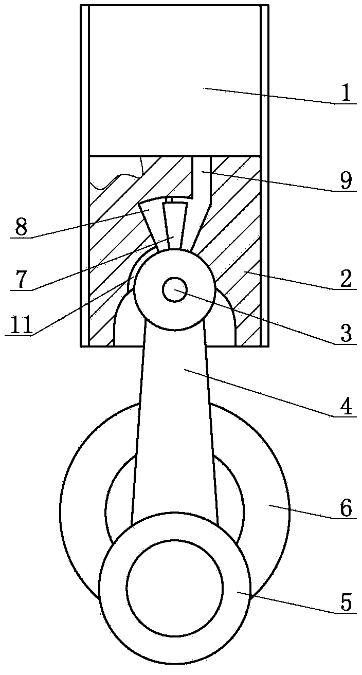
[0009] The connecting rod-piston combined combustion chamber of the present invention has no dead point reciprocating internal combustion engine, such as figure 1 Shown includes housing, connecting rod 4, crank 5, crankshaft 6. The housing is provided with a cylinder 1 . A piston head 2 is installed in the cylinder 1. An inner cavity 13 and a piston pin hole 17 are provided in the piston head 2 . Piston head 2 is hinged with connecting rod 4 through piston pin 3 . The piston pin 3 cooperates with the piston pin hole 17, and the connecting rod 4 is located in the inner chamber 13. Such as Figure 5 As shown, the end of the piston head 2 offers an air inlet 9. A crown-shaped gas chamber 8 and an air channel 11 are provided in the piston head 2 . The air passage 11 communicates with the crankcase 16 of the cylinder 1 . A piston block 7 is provided at the hinged end of the connecting rod 4 and the piston pin 3 . Such as Figures 1 to 4 As shown, the piston block 7 coopera...


PUM


Abstract

The invention discloses a connecting rod piston type combustion chamber combined dead-center-free reciprocating internal combustion engine which comprises a shell, a connecting rod, a crank and a crankshaft. A cylinder is arranged in the shell, a piston head is mounted in the cylinder, an inner cavity and a piston pin hole are formed in the piston head, the piston head is hinged to the connecting rod through a piston pin which is matched with the piston pin hole, and the connecting rod is located in the inner cavity. Smoothness of the internal combustion engine can be effectively improved, and service life of the internal combustion engine is prolonged. The dead center distance with the top dead center position about 15-25 degrees of an original internal combustion engine is utilized, working stroke of an original conventional piston is elongated, and thrust area of the piston is increased, so that the internal combustion engine is ensured to output power under maximum pressure. The piston head, the piston pin and the connecting rod can act for power output at an angle more than 180 degrees, particularly power output with piston running top and bottom dead centers of crankshaft 180 degrees + piston block output thrust angle of crank angle 90 degrees more than and equal to crank angle 180 degrees. Dead centers are eliminated, and the connecting rod piston type combustion chamber combined dead-center-free reciprocating internal combustion engine further has the advantages of simple structure and simplicity in manufacturing.

Description

technical field [0001] The invention relates to an internal combustion engine, specifically a reciprocating internal combustion engine with a connecting rod and piston type combined combustion chamber without dead point. Background technique [0002] The existing piston reciprocating internal combustion engine has the problem of a dead point when the piston moves downward at the top dead center during the power stroke. The main reason is that the thrust direction of the traditional internal combustion engine piston can only be the downward direction of the piston, that is, the piston cannot transmit thrust to multiple directions. When the piston travels to the top dead center, the thrust will not only do no work but also directly act on the crankshaft, increasing the load on the crankshaft, causing damage to the crankshaft and the entire internal combustion engine in varying degrees, thereby shortening the service life of the internal combustion engine. Contents of the in...

Claims


Application Information

Patent Timeline
Patent Type & Authority Applications(China)
IPC IPC(8): F02B75/40F02B75/32F02F3/00
CPCF02B41/04
Inventor 尹建尹佳琳
Owner 尹建
Learn More