
Tide power generation device

A tidal power generation and generator technology, applied in the directions of hydropower generation, ocean energy power generation, renewable energy power generation, etc., can solve the problems of low energy utilization rate and power generation efficiency, and achieve the effect of improving water energy utilization rate and power generation efficiency.

Inactive Publication Date: 2014-04-23
钱成结
View PDF8 Cites 2 Cited by
  • Summary
  • Abstract
  • Description
  • Claims
  • Application Information

AI Technical Summary

Problems solved by technology

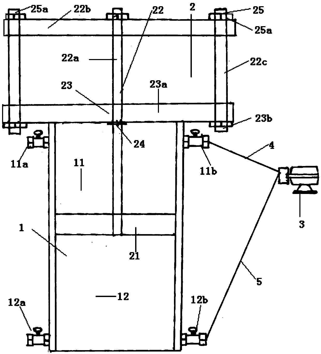
[0005] For this reason, the technical problem to be solved by the present invention is to overcome the defect that the tidal power generation device in the prior art can only complete one power generation after a cycle of rising tide and ebb tide, resulting in low energy utilization rate and power generation efficiency, thereby providing a A tidal power generation device that can generate electricity not only when the tide rises, but also when the tide falls

Method used


Image

  • Tide power generation device

Examples


Embodiment 1

[0038] Such as figure 1 As shown, this embodiment provides a tidal power generation device, the tidal power generation device includes a pressure pipeline 1 and an adjustment device 2 sealingly connected with the pressure pipeline 1, wherein the adjustment device 2 includes 1 inside and divides the pressure pipe 1 into a first closed chamber 11 and a second closed chamber 12, and a piston 21 connected with the piston 21 and able to drive the piston 21 along the pressure line when the tide rises and falls. The pipe 1 moves axially to change the internal pressure of the first closed chamber 11 and the second closed chamber 12. The pressure pipe 1 is provided with a first smart valve at a position corresponding to the first closed chamber 11. The water inlet valve 11a and the first intelligent water outlet valve 11b, the second intelligent water inlet valve 12a and the second intelligent water outlet valve 12b are arranged on the pressure pipe 1 corresponding to the second closed...

Embodiment 2

[0056] This embodiment provides a tidal power generation device, which is a deformation on the basis of Embodiment 1. The pressure sensing element is different from Embodiment 1. In this embodiment, the first intelligent water inlet valve 11a and the The second intelligent water outlet valve 12b is respectively provided with pressure sensing elements; the second intelligent water inlet valve 12a and the first intelligent water outlet valve 11b are also respectively provided with pressure sensing elements. When the tide rises, the pressure sensor senses the pressure in the first closed cavity 11 and the second closed cavity 12 respectively, so as to realize the independent opening of the second intelligent water inlet valve 12a and the first intelligent water outlet valve 11b; At this time, the pressure sensing element senses the pressure in the first closed chamber 11 and the second closed chamber 12 respectively, so as to realize the independent opening of the second smart wat...


PUM


Abstract

The invention discloses a tide power generation device. The tide power generation device comprises a pressure pipeline and an adjusting device which is seal connection with the pressure pipeline; interior pressure of a first sealing chamber and a second sealing chamber inside the pressure pipeline is changed due to continuous movement of the adjusting device; a first intelligent water inlet valve and a second intelligent water outlet valve on the pressure pipeline are started and the second intelligent water outlet valve is communicated with an electric generator when the tide falls; a second water inlet valve and a first intelligent water outlet valve of the pressure pipeline are started when the tide rises and the first intelligent water outlet valve is communicated with the electric generator. The tide power generation device has the advantages of effectively guaranteeing balancing of water feeding and water discharging of the pressure pipeline, accordingly achieving continuous circulation of the power generation technology and allowing power generation every time the tide rises or the tide falls.

Description

technical field [0001] The invention relates to a tidal power generation device, which belongs to the technical field of tidal power generation. Background technique [0002] With the development of science and technology, human beings have an increasing demand for energy, and the exploitation and use of chemical energy sources such as oil, natural gas, and coal have brought huge damage to the environment. The continuous consumption of renewable energy makes it increasingly exhausted. Therefore, it is urgent to find clean, pollution-free and renewable alternative energy to achieve sustainable energy development. [0003] Taking power generation as an example, at present, many regions in my country still use traditional coal power generation technology. Although coal power generation technology is relatively mature, the harmful gases emitted by it are particularly serious for environmental pollution. In recent years, the smog that has appeared in most parts of the country It ...

Claims


Application Information

Patent Timeline
IPC IPC(8): F03B13/26F03B11/00
CPCY02E10/226Y02E10/20Y02E10/30
Inventor 徐力李晓乐徐顺宝钱成结
Owner 钱成结
Learn More