
Water collecting device for nuclear power plants and high tower with same

A water collection device and nuclear power plant technology, applied in the field of high-level towers, can solve problems such as high head of circulating water pumps, loud noise in rainy areas, and deterioration of cavitation conditions, and achieve the goals of saving installation engineering, reducing pump head, and reducing noise levels Effect

Active Publication Date: 2014-04-23
中广核工程有限公司 +1
View PDF6 Cites 10 Cited by
  • Summary
  • Abstract
  • Description
  • Claims
  • Application Information

AI Technical Summary

Problems solved by technology

[0007] 1. High head of the circulating water pump: In addition to providing the along-course and local head loss during the cooling water circulation process, the circulating water pump also needs to provide the static head of the water level of the distribution well including the height of the rain area;
[0008] 2. The noise in the rain area is large: the larger the tower, the higher the height of the rain area, and the greater the noise in the rain area. According to the measured data, 12000m 2 The noise at the side of the conventional natural ventilation cooling tower reaches 80dB, which has a great impact on the work and life of the residents around the cooling tower or on duty;
[0009] 3. The existence of the rain area makes the resistance of the air entering the packing gradually increase, and with the increase of the tower area, the longer the air travels through the rain area, the more difficult it becomes for the central area of ​​the tower to require a sufficient amount of cold air , if the height of the air inlet is raised unilaterally, the problems 1 and 2 will be exacerbated, and the cost of the tower will increase;
[0013] In addition, conventional plastics or even concrete materials are generally used for water collection plates and water collection tanks, which fail to select materials in a targeted manner according to the different functions and corrosion failure modes of the components, resulting in failure of vulnerable and corrosive components, resulting in shutdown of the pump or The water body is aerated, and the cavitation condition of the pump operation deteriorates

Method used


Image

  • Water collecting device for nuclear power plants and high tower with same
  • Water collecting device for nuclear power plants and high tower with same
  • Water collecting device for nuclear power plants and high tower with same

Examples


Embodiment Construction

[0054] In order to make the purpose of the invention, technical solution and beneficial technical effects of the present invention clearer, the present invention will be further described in detail below in conjunction with the accompanying drawings and specific implementation methods. It should be understood that the specific implementations described in this specification are only for explaining the present invention, not for limiting the present invention.

[0055] Before carrying out the description of the present invention, first explain the theoretical basis of the present invention, and the present invention comes from the inspiration of the arrangement of leaves. In order to obtain sufficient photosynthesis and respiration, the leaves need to fully stretch the leaf surface itself, so that the leaves can maintain the maximum light-receiving surface. In order to satisfy the same photosynthesis and respiration for different phyllotaxy leaves, the most common and effective...


PUM


Abstract

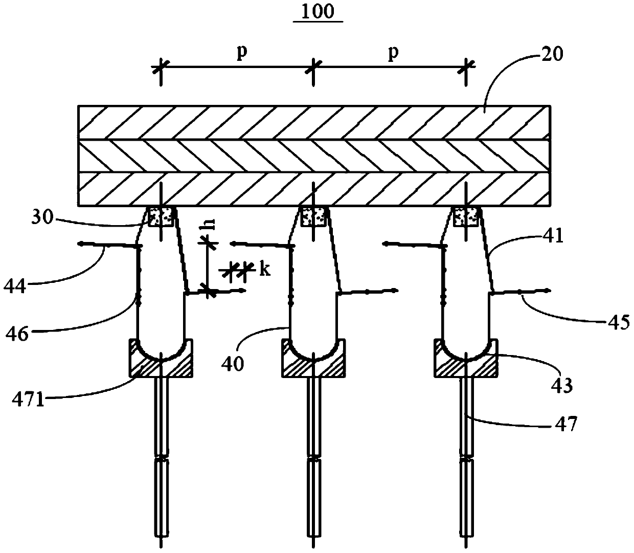
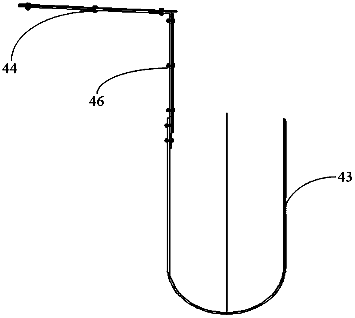
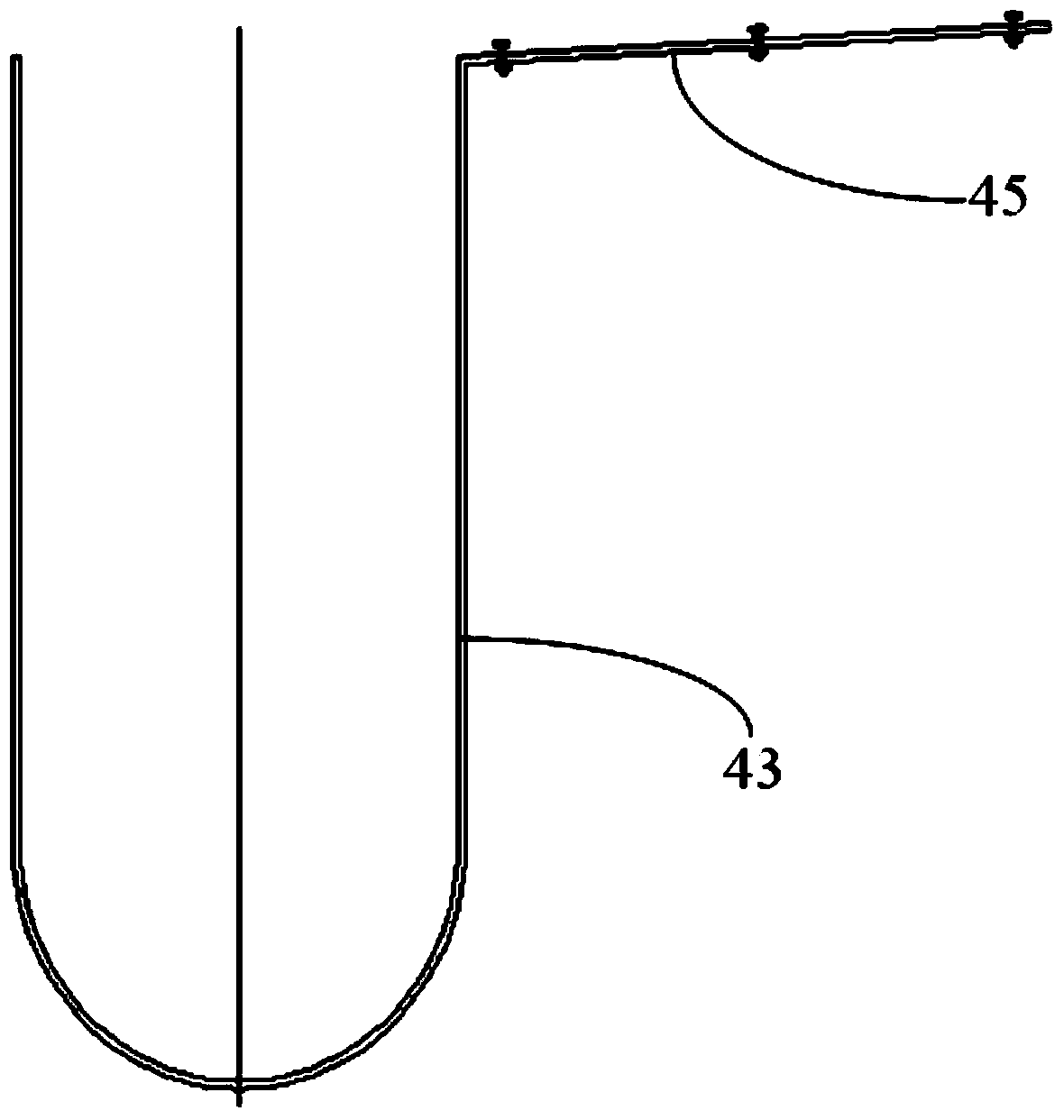
The invention discloses a water collecting device for nuclear power plants and a high tower with the same. The water collecting device is used for collecting fallen cooling water from rain filler. The water collecting comprises a plurality of horizontal abreast-staggered water collecting units. The water collecting units comprise hanging rods, supports, water collecting tanks, high-level water collecting plates, low-level water collecting plates and junction plates. One ends of the hanging rods are suspended on a supporting beam, the other ends of the hanging rods are connected to the supports, the water collecting tanks, the high-level water collecting plates, the low-level water collecting plates and the junction plates are connected to the supports, the high-level water collecting plates and the low-level water collecting plates are arranged in a staggered manner from top to bottom, the high-level water collecting plates are communicated with the water collecting tanks through the junction plates, and the low-level water collecting plates are communicated with the water collecting tanks directly. The water collecting device for nuclear power plant and the high tower with the same have the advantages that lift of a circulating pump can be reduced, noise can be lowered and cold air can enter the filler freely.

Description

technical field [0001] The invention relates to a composition structure of a high-level tower for a nuclear power plant, more specifically, the invention relates to a water collection device for a nuclear power plant and a high-level tower including the water collection device. Background technique [0002] Cooling towers are widely used industrial and civil cooling equipment. Among electric cooling equipment, cooling towers are used the most. The hot water of conventional cooling towers goes through three parts: the spray area, the water film area and the rain area during the cooling and falling process. The high-level tower shortens the rain area by elevating the water collection device, thereby reducing the head of the circulating water pump, saving pump power, and reducing noise in the rain area. It is no longer necessary to consider that with the increase of the diameter of the cooling tower, the cold air passes through the rain area for too long, resulting in the centra...

Claims


Application Information

Patent Timeline
Patent Type & Authority Applications(China)
IPC IPC(8): F28F25/02F28C1/00
Inventor 程道仓孙一奇南卫胡少华吴庆旺吴襄竹王志明曹永旺辛文军齐文明
Owner 中广核工程有限公司
Learn More