Supercharge Your Innovation With Domain-Expert AI Agents!

Automatic machining and feeding system for metal bars

A technology of metal rods and material boxes, applied in metal processing equipment, manufacturing tools, operating devices, etc., can solve the problems of insufficient coordination of workers, lower yield rate, high probability of misoperation, etc., to improve high temperature operation risk and production efficiency The effect of improving and reducing the chance of misoperation

Active Publication Date: 2014-04-30
广州意戈力自动化设备有限公司 +1
View PDF5 Cites 14 Cited by
  • Summary
  • Abstract
  • Description
  • Claims
  • Application Information

AI Technical Summary

Problems solved by technology

[0003] 1. The probability of misoperation is high: because a large number of bars are piled up in boxes, it is easy to cause artificial misplacement of different workpiece sizes into the material basket, and the heating time will be different due to different material sizes, which will lead to unstable heating and product quality problems ;
[0004] 2. Low safety: Since the production mode adopts manual pick-and-place, it is easy for workers to burn and scald due to worker misuse or fatigue on high-temperature materials, or to cause disability when fingers are pressed when operating the hot forging machine;
[0005] 3. Low production efficiency: the current production mode takes 65 seconds to process a metal bar;
[0006] 4. Low rate of good products: Since the existing production method requires three workers to operate at the same time, that is, pick up and feed materials, feed heated workpieces, and unload hot forged workpieces separately, this will lead to insufficient coordination in production And reduce the yield rate, the yield rate only reached 75%;
[0007] 5. Large energy loss: due to manual operation, usually due to lack of coordination of workers, the heating mechanism runs empty, resulting in a large waste of energy

Method used


Image

  • Automatic machining and feeding system for metal bars
  • Automatic machining and feeding system for metal bars
  • Automatic machining and feeding system for metal bars

Examples


Embodiment Construction

[0048] In order to make the technical solution of the present invention clearer, the present invention will be described in detail below through specific embodiments in conjunction with the accompanying drawings.

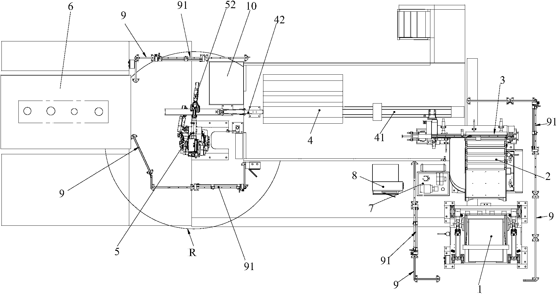
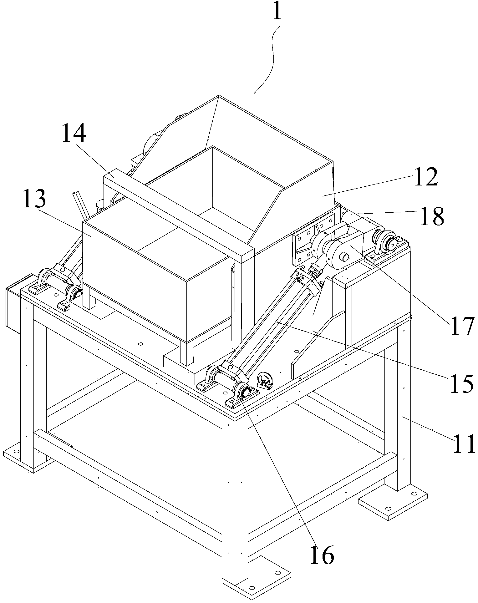
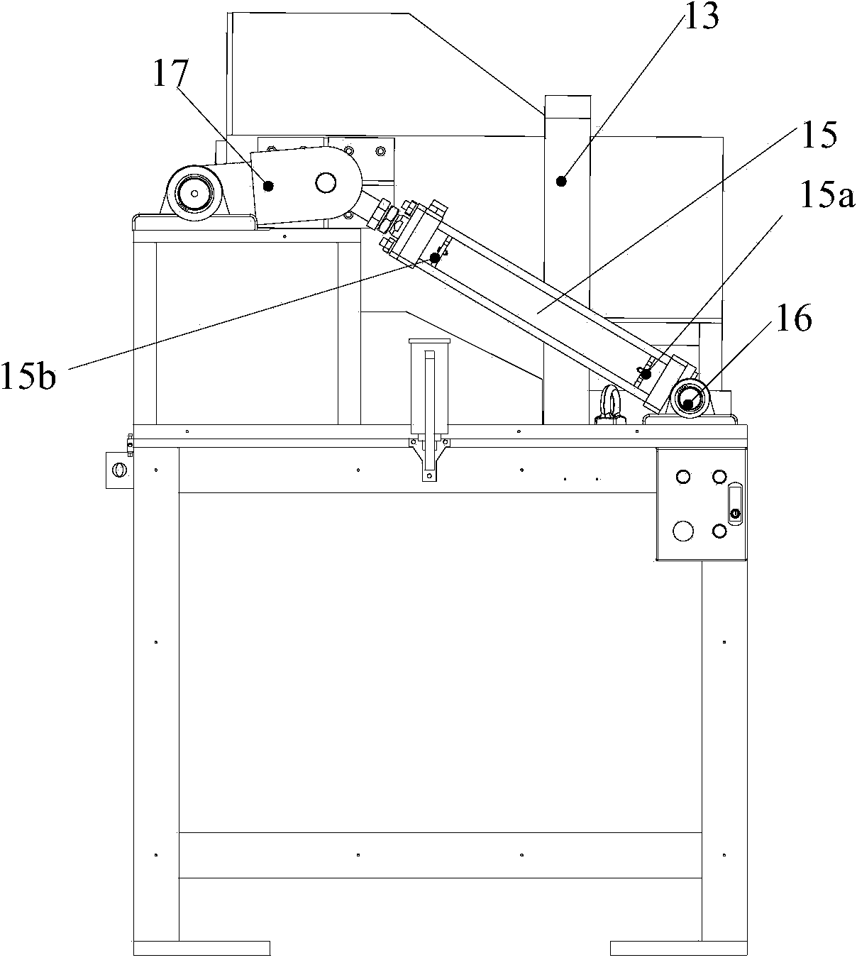
[0049] See Figure 1 ~ Figure 15 , The metal bar material automatic processing and feeding system in this embodiment includes the following components: flipping and dumping mechanism 1, monolithic arrangement mechanism 2, conveying detection mechanism 3, heating mechanism 4, robot 5, hydraulic station 7, control cabinet 8. , The robot 5 is set close to the forging press 6; the robot 5 is surrounded by a safety guardrail 9, the overturning and dumping mechanism 1, the whole material arrangement mechanism 2, the conveying detection mechanism 3 is also surrounded by a safety guardrail 9, and the safety guardrail 9 is provided There are 91 sliding doors. Wherein, the hopper of the material turning and unloading mechanism 1 is arranged close to the storage lifting hopper of...


PUM


Abstract

The invention discloses an automatic machining and feeding system for metal bars. The system comprises a turnover discharging mechanism, an arranging and lifting mechanism, a conveying detection mechanism, a heating mechanism and a robot. The turnover discharging mechanism is provided with a base and a turnover rack capable of rotating around the base, and the turnover rack is used for fixing a work bin loaded with the metal bars. The arranging and lifting mechanism is used for receiving the metal bars falling down from the work bin in the turnover rack rotating process, and arranging and lifting the metal bars to the top outlet of the arranging and lifting mechanism. The conveying detection mechanism is used for receiving the metal bars falling down from the top outlet of the arranging and lifting mechanism, conveying the metal bars forwards, and filtering out the metal bars which do not accord with the preset lengths and preset diameters. The heating mechanism is used for heating the metal bars conveyed through the conveying mechanism. The robot is provided with a clamping mechanism, wherein the clamping mechanism is provided with a clamping hand used for clamping the metal bars heated by the heating mechanism, and the clamping hand is provided with at least two clamping fingers. The automatic machining and feeding system can improve production efficiency, product percent of pass and safety.

Description

Technical field [0001] The invention relates to the technical field of metal bar material processing equipment, in particular to a metal bar material automatic processing and feeding system. Background technique [0002] At present, in the production process of metal parts, it is necessary to cut the raw material-metal bar, and then use a heating mechanism to heat it to a predetermined temperature, and finally send it to a hot forging machine for forging. In the prior art, when metal bars are hot forged, manual methods are generally used, that is, workers cut the metal bars through a cutting machine and then are sent to the conveyor belt by a conveyor device, and then the cut metal bars are manually processed Send it into the heating laser for heating until about 1450℃. After sending it out, manually send the heated metal bar into the hot forging machine with a high temperature resistant fixture. This manual operation has the following defects: [0003] 1. The probability of misop...

Claims


Application Information

Patent Timeline
IPC IPC(8): B21K27/02
Inventor 郭文洲
Owner 广州意戈力自动化设备有限公司
Features
  • R&D
  • Intellectual Property
  • Life Sciences
  • Materials
  • Tech Scout
  • Unparalleled Data Quality
  • Higher Quality Content
  • 60% Fewer Hallucinations
Learn More