Ball high-speed motorized spindle

A high-speed motorized spindle and ball technology, used in large fixed members, maintenance and safety accessories, drive devices, etc., can solve the problems of short service life, limited effect, and poor sealing effect of the sealing rubber ring, so as to improve the running accuracy, improve the Lubrication effect, effect of increasing service life

Active Publication Date: 2014-04-30
GUANGZHOU HAOZHI ELECTROMECHANICAL
View PDF7 Cites 10 Cited by
  • Summary
  • Abstract
  • Description
  • Claims
  • Application Information

AI Technical Summary

Problems solved by technology

[0005] At present, the high-speed rotation of the electric spindle mainly depends on the upper bearing and the lower bearing matched by the upper bearing seat and the lower bearing seat at both ends of the shaft core. The inner ring and the outer ring of the upper bearing and the lower bearing are filled with grease to ensure that the electric spindle The shaft core rotates at a high speed. This method of lubrication has high requirements on the performance of the grease, and the lubricating effect of the grease is not ideal after a long time of use, which affects the rotation speed of the electric spindle. In order to improve the rotation efficiency of the electric spindle, The existing improvements are all achieved by improving the performance of the grease, therefore, the improvement effect is relatively limited
At the same time, at present, the rotary joint part of the electric spindle adopts a contact-type cooperation with the shaft core, and there is sliding friction between the rotary joint and the high-speed rotating shaft core, which limits the rotation rate of the shaft core to a certain extent; in addition, the existing The shaft core and the rotary joint adopt the contact sealing method, the sealing effect is poor, and some coolant will still enter the electric spindle through the gap. At the same time, this contact sealing usually relies on the sealing rubber ring. When rotating, the wear of the sealing rubber ring is serious, resulting in a shorter service life of the sealing rubber ring

Method used


Image

  • Ball high-speed motorized spindle
  • Ball high-speed motorized spindle
  • Ball high-speed motorized spindle

Examples


Embodiment Construction

[0036] Below, in conjunction with accompanying drawing and specific embodiment, the present invention is described further:

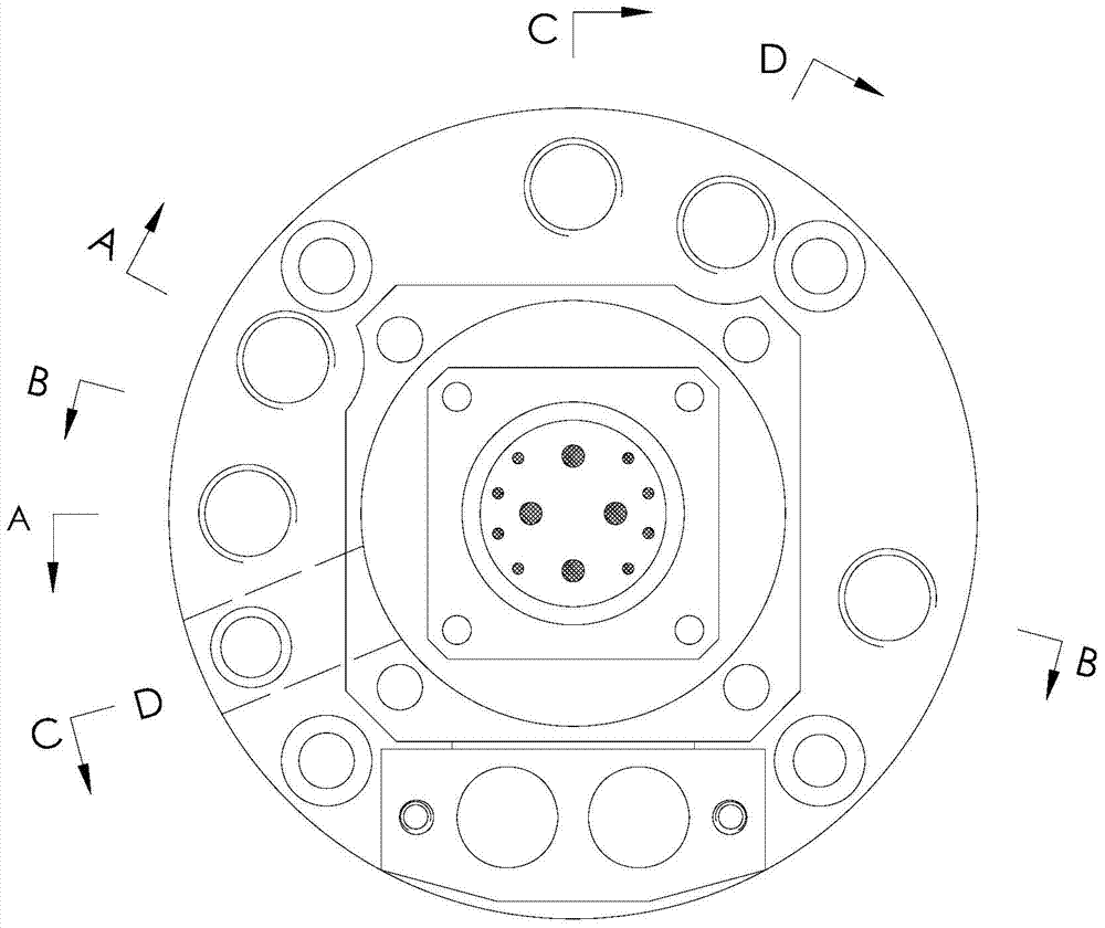
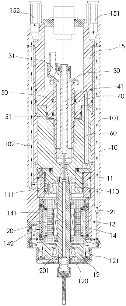
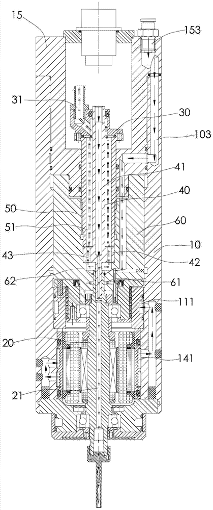
[0037] see figure 1 , 2 , 3, 4, 5, the ball high-speed electric spindle of the present invention includes a body assembly and a shaft core assembly, wherein the body assembly includes a body 10, an upper bearing seat 11, a lower bearing seat 12, a stator 13, and a heat conduction sleeve 14, wherein, Both the body 10 and the heat conduction sleeve 14 are in a cylindrical shape, the heat conduction sleeve 14 is fixed inside the body 10, and its outer surface is tightly bonded to the inner surface of the body 10, the stator 13 is fixed inside the heat conduction sleeve 14, the upper bearing seat 11 and the lower The bearing blocks 12 are all fixedly connected with the machine body 10 .

[0038] The outer surface of the heat conduction sleeve 14 is provided with a first annular cooling groove 141 and a second annular cooling groove 142 surrounding the out...


PUM


Abstract

A ball high-speed motorized spindle comprises a unit component which comprises a body, a stator fixed in the unit and an upper bearing block and a lower bearing block which are fixedly connected onto the unit. A shaft core component comprises a shaft core and a rotor which is mounted on the outside of the shaft core and matched with the stator. The upper end of the shaft core is pivoted to the upper bearing block through an upper bearing, and the lower end is pivoted to the lower bearing block through a lower bearing. An upper lubrication oil gas inlet, a lower lubrication oil gas inlet and a lubrication oil gas outlet are formed in the body component. Gaps between the upper lubrication oil gas inlet and an upper bearing inner ring and outer ring and the lubrication oil gas outlet are communicated successively. Gaps between the lower lubrication oil gas inlet and a lower bearing inner ring and outer ring and the lubrication oil gas outlet are communicated successively. According to the ball high-speed motorized spindle, channels for delivering oil gas lubrication media to the upper bearing and the lower bearing are arranged in the ball high-speed motorized spindle to deliver oil gas lubrication media to the upper bearing and the lower bearing continuously, so that the lubrication effect is improved.

Description

[0001] technical field [0002] The invention relates to a ball high-speed electric spindle applied in the field of mechanical processing. [0003] Background technique [0004] The electric spindle is a commonly used equipment for mechanical processing. It usually includes the body and the shaft core assembly. The shaft core assembly is installed inside the body. The shaft core assembly rotates at high speed, and an upper bearing seat and a lower bearing seat are fixed on the body, and the two ends of the shaft core assembly are pivotally connected to the upper bearing seat and the lower bearing seat through the upper bearing and the lower bearing respectively. [0005] At present, the high-speed rotation of the electric spindle mainly depends on the upper bearing and the lower bearing matched by the upper bearing seat and the lower bearing seat at both ends of the shaft core. The inner ring and the outer ring of the upper bearing and the lower bearing are filled with grea...

Claims


Application Information

Patent Timeline
Patent Type & Authority Applications(China)
IPC IPC(8): B23B19/02B23Q11/12
CPCB23Q5/10B23Q11/123B23Q1/70
Inventor 汤秀清
Owner GUANGZHOU HAOZHI ELECTROMECHANICAL
Why Eureka
Try Eureka