
Method for controlling welding deformation of telescopic steering oar base seat barrel

A welding deformation and telescopic technology, applied in welding equipment, manufacturing tools, instruments, etc., can solve the problems of affecting the flatness of flanges, rework of base installation, and difficulty in controlling welding deformation of cylinders, so as to reduce assembly accuracy and reduce The difficulty of construction and the effect of shortening the cycle in the dock

Active Publication Date: 2014-04-30
QINGDAO WUCHUAN HEAVY IND CO LTD
View PDF6 Cites 8 Cited by
  • Summary
  • Abstract
  • Description
  • Claims
  • Application Information

AI Technical Summary

Problems solved by technology

The existing base installation process usually strictly controls the assembly accuracy of the cylinder, and adopts the construction method of symmetrical welding with even numbers of welders. Due to the large cylinder, the assembly accuracy of the cylinder is difficult to control, and the installation and construction of the base is time-consuming and laborious. Moreover, it is difficult to control the welding deformation of the cylinder during the installation and construction process. Once the cylinder is welded and deformed, the horizontal plane of the flange will be distorted and deformed, which will affect the flatness of the flange, resulting in a large number of rework during the installation process of the base, and even the rework of the entire base. manufacture

Method used


Image

  • Method for controlling welding deformation of telescopic steering oar base seat barrel
  • Method for controlling welding deformation of telescopic steering oar base seat barrel
  • Method for controlling welding deformation of telescopic steering oar base seat barrel

Examples


Embodiment Construction

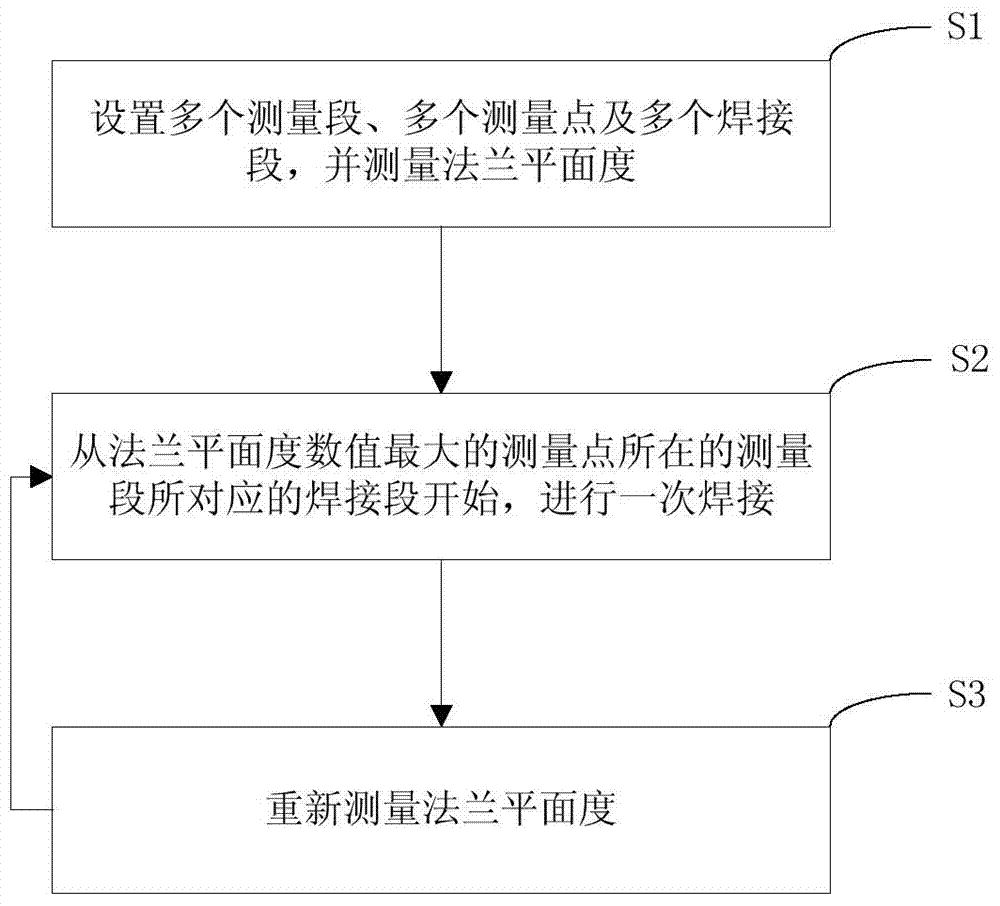
[0021] Such as figure 1 As shown, the present invention is a method for controlling the welding deformation of the telescopic rudder oar base cylinder, the telescopic rudder oar base includes a cylinder and a flange, the flange is horizontally arranged on the top of the cylinder, and the cylinder The bottom end of the body is welded to the hull, and when the bottom end of the cylinder body is welded to the hull, it specifically includes the following steps:

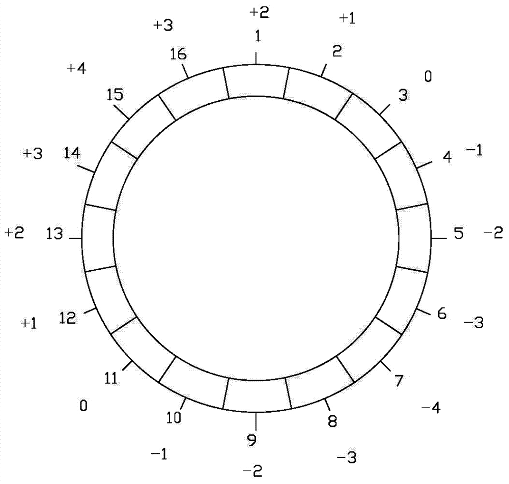
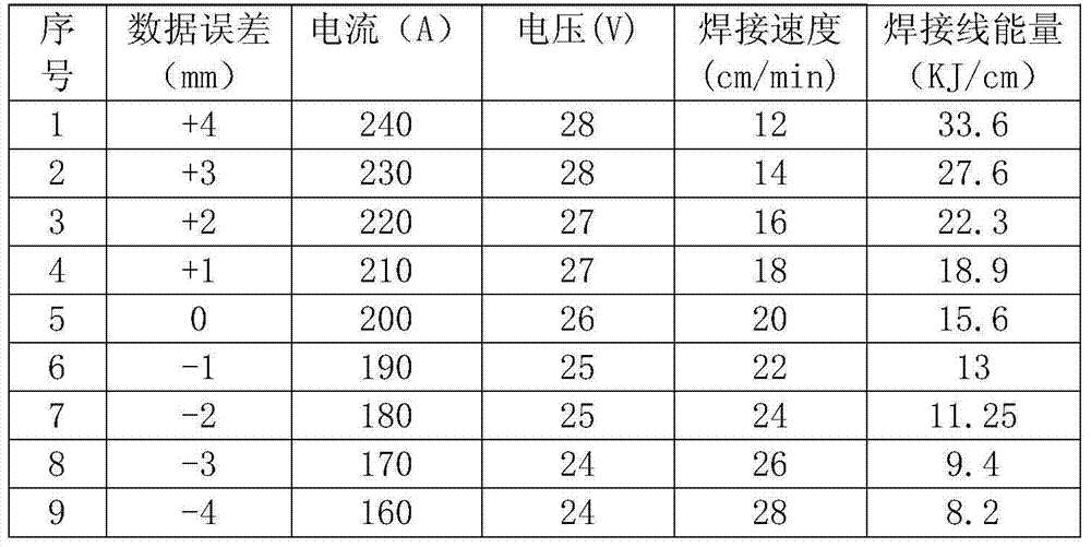
[0022] S1. Divide the outer perimeter of the top of the cylinder into multiple measuring sections. The number of measuring sections increases according to the diameter of the cylinder. A measuring point is set in the middle of each measuring section. The outer perimeter of the bottom of the cylinder is the same as A plurality of welding sections are set corresponding to the plurality of measuring sections one by one, and each measuring point has a corresponding projection point on the welding section, and the flatness of ...


PUM

PropertyMeasurementUnit
Diameteraaaaaaaaaa

Abstract

The invention discloses a method for controlling welding deformation of a telescopic steering oar base seat barrel, and relates to the material molding and controlling filed. The method for controlling the welding deformation of the telescopic steering oar base seat barrel includes steps: S1, equally dividing the outer perimeter of the top of the barrel into a plurality of measurement segments, setting a measurement point in the middle position of each measurement segment, arranging a plurality of welding segments which are in one to one correspondence with the plurality of the measurement segments on the outer perimeter of the bottom of the barrel, and measuring flatness of a flange through each measurement point; S2, starting from the welding segment corresponding to the measurement segment where the measurement point with the maximal flatness value of the flange is located to perform welding once, and welding at least one welding segment every time; S3, after welding once, re-measuring the flatness of the flange, moving to the step S2 to perform welding once again, and repeating the step 2 and the step 3 until welding of all the welding segments are finished. The method for controlling the welding deformation of the telescopic steering oar base seat barrel reduces assembly accuracy of the barrel, improves production efficiency, and effectively controls the flatness of the flange.

Description

technical field [0001] The invention relates to the field of material forming and control, in particular to a method for controlling the welding deformation of a telescopic rudder propeller base cylinder. Background technique [0002] The telescopic rudder propeller base of large engineering ships such as "deep diving working mother ship" and "3200-ton double-arm frame luffing crane ship" is composed of a cylinder and a flange. welded to the hull. The installation precision of the base is higher, especially the flatness of the flange is higher, and the maximum flatness error is not more than 1.5mm. The existing base installation process usually strictly controls the assembly accuracy of the cylinder, and adopts the construction method of symmetrical welding with even numbers of welders. Due to the large cylinder, the assembly accuracy of the cylinder is difficult to control, and the installation and construction of the base is time-consuming and laborious. Moreover, it is ...

Claims


Application Information

Patent Timeline
IPC IPC(8): B23K31/02G01B11/30
CPCB23K31/02G01B11/30
Inventor 吕德华刘海清
Owner QINGDAO WUCHUAN HEAVY IND CO LTD
Learn More