Laser scanning-vibration hot wire TIG hybrid welding method

A technology of laser scanning and composite welding, which is applied in the field of welding processing, can solve the problems of low deposition rate and welding efficiency, high requirements for welding and assembly precision, and low requirements for assembly precision, so as to reduce the solidification speed, reduce the assembly precision, and reduce the heating range. wide effect

Inactive Publication Date: 2020-04-07
HARBIN INST OF TECH AT WEIHAI
View PDF13 Cites 7 Cited by
  • Summary
  • Abstract
  • Description
  • Claims
  • Application Information

AI Technical Summary

Problems solved by technology

[0004] In order to solve the technical problems of existing laser welding such as many pores defects, large welding crystal grains, high welding assembly precision, low deposition rate and low welding efficiency, the present invention provides a low assembly precision before welding and high welding efficiency. , a laser scanning-vibrating hot wire TIG hybrid welding method that simultaneously reduces porosity and refines the structure

Method used


Image

  • Laser scanning-vibration hot wire TIG hybrid welding method
  • Laser scanning-vibration hot wire TIG hybrid welding method

Examples


Embodiment 1

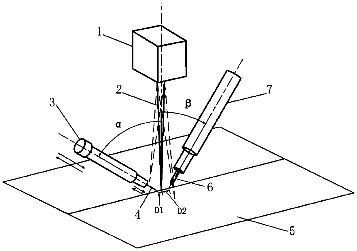
[0027] Such as figure 1 As shown, the scanning laser beam 2 is perpendicular to the welding plate, the wire feed gun 3 and the TIG welding gun 7 are located on both sides of the scanning laser beam 2, and the angle α between the wire feed gun 3 and the scanning laser beam 2 is 15°~75°, TIG The angle β between the welding gun 7 and the scanning laser beam 2 is 15°-60°, and the distances D1 and D2 between the scanning laser beam 2 and the heating wire 4 and the tungsten electrode 6 are 0-8mm and 0-10mm, respectively. Taking the X axis parallel to the welding seam direction as the Y axis perpendicular to the welding seam direction, the scanning laser beam 2 swings from -5mm to +5mm along the X axis and from -5mm to +5mm along the Y axis. The swing frequency is 10~1500Hz. The laser power can be 50 to 10000W, and the arc power can be 10 to 12000W. The current of the hot wire 4 is 0-180A, the wire feeding speed is 0-10m / min, the amplitude of the hot wire 4 along the wire direction i...

Embodiment 2

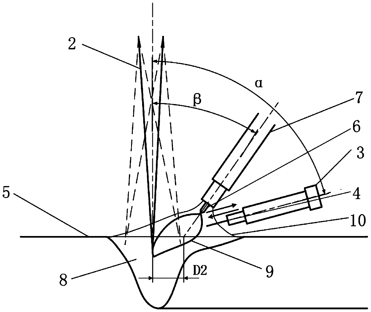
[0030] Such as figure 2 As shown, the scanning laser beam 2 is perpendicular to the welding plate, the wire feed gun 3 and the TIG welding torch 7 are respectively located on the same side of the scanning laser beam 2, the angle α between the wire feed gun 3 and the scanning laser beam 2 is 15°~75°, TIG The angle β between the welding gun 7 and the scanning laser beam 2 is 15°-60°, and the distances D1 and D2 between the scanning laser beam 2 and the heating wire 4 and the tungsten electrode 6 are 0-8mm and 0-10mm, respectively. Taking the X axis parallel to the welding seam direction as the Y axis perpendicular to the welding seam direction, the scanning laser beam 2 swings from -5mm to +5mm along the X axis and from -5mm to +5mm along the Y axis. The swing frequency is 10~1500Hz. The laser power can be 50 to 10000W, and the arc power can be 10 to 12000W. The current of the hot wire 4 is 0-180A, the wire feeding speed is 0-10m / min, the amplitude of the hot wire 4 along the ...


PUM

PropertyMeasurementUnit
laser poweraaaaaaaaaa

Abstract

The invention relates to a laser scanning-vibration hot wire TIG hybrid welding method. The method is mainly formed by compounding laser scanning welding and vibration hot wire TIG welding. During welding, a welding heat source is formed by combining a scanning laser and a TIG electric arc, a welding wire is heated and vibrated in a reciprocating mode at the same time so as to generate a vibrationhot wire, and laser scanning-vibration hot wire TIG hybrid welding is jointly formed by the vibration hot wire and a hybrid heat source. According to the method, on one hand, the laser scanning welding can reduce an assembling precision requirement of a workpiece before welding; and on the other hand, a stirring effect on a molten pool can reduce a porosity and refine a structure; and heat inputduring welding can be reduced by preheating the welding wire, and a deposition rate and welding efficiency are improved. Under a condition that the hot wire is vibrated, on one hand, a molten pool canbe stirred to refine the structure; and on the other hand, a molten drop transition frequency can be increased, and the welding efficiency is improved.

Description

Technical field [0001] The invention relates to the technical field of welding processing, in particular to a laser scanning-vibration hot wire TIG composite welding method. Background technique [0002] With the continuous development and progress of the industrial level of today's society, industrial equipment is becoming larger and larger, which puts forward higher requirements for welding efficiency and quality. Traditional arc welding has small penetration depth, low efficiency, large spatters during welding, coarse structure after welding, and wide heat-affected zone, which affect the weld performance; while laser welding can achieve deep penetration welding and high welding efficiency, but high density Laser energy puts forward very high requirements on the assembly accuracy of the workpiece before welding, and there are often many pore defects in the deep and narrow weld seam of laser welding; laser arc hybrid welding that combines arc welding and laser welding overcomes ...

Claims


Application Information

Patent Timeline
Patent Type & Authority Applications(China)
IPC IPC(8): B23K26/348B23K26/70
CPCB23K26/348B23K26/702
Inventor 陈波陈志伟马程远檀财旺冯吉才
Owner HARBIN INST OF TECH AT WEIHAI
Why Eureka
Try Eureka