Graded storage injection molding machine

An injection molding machine and material storage technology, applied in the field of graded material storage injection molding machines, can solve the problems of low hydraulic system efficiency, reduced service life, and quality fluctuations, and achieve precise control, energy saving, improved service life, and stable plasticizing quality. Effect

Active Publication Date: 2014-04-30
广东福能精密机械有限公司
View PDF6 Cites 7 Cited by
  • Summary
  • Abstract
  • Description
  • Claims
  • Application Information

AI Technical Summary

Problems solved by technology

[0004] 1. High ineffective energy consumption
Plasticization is driven by a hydraulic motor to drive the screw to rotate. In order to meet the requirements of different working conditions (injection volume, material properties, plasticization time, etc.), the hydraulic motor must work at different speeds, and often starts and stops intermittently. The efficiency of the hydraulic system in the process is very low or even generates a lot of heat, and an additional powerful cooling system is required to cool the oil temperature
[0005] 2. Plasticizing quality is not stable
Because the traditional working mechanism relies on the intermittent working method of screw rotation plasticization-stop-rerotation plasticization, the plasticization of materials is often unstable and the quality fluctuates.
[0006] 3. Slow working speed
As mentioned earlier, because the machine works intermittently, the oil motor and screw are often in a standby state, and their working capacity has not been maximized
[0007] 4. High failure rate
Since the oil motor is in the state of frequent start and stop, there will be a large torque impact every time it is started, which will cause fatigue damage to the motor, hydraulic components, screws, etc., and the service life will be reduced
[0008] 5. High cost
The cost of working oil pumps, oil motors, hydraulic control components, etc. is relatively high

Method used


Image

  • Graded storage injection molding machine
  • Graded storage injection molding machine
  • Graded storage injection molding machine

Examples


Embodiment Construction

[0038] The present invention will be further described with embodiment below in conjunction with accompanying drawing.

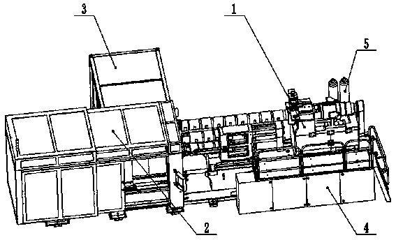
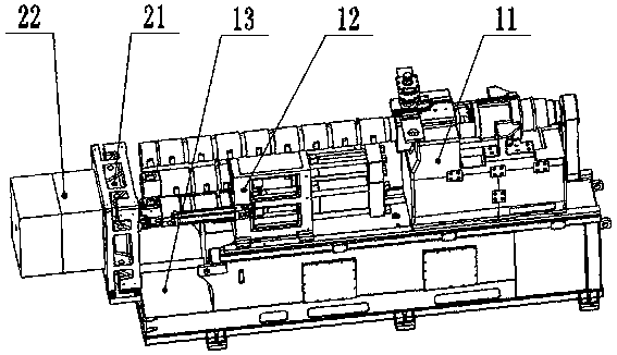
[0039] Such as figure 1 and figure 2 As shown, the present invention provides a kind of graded storage injection molding machine, which comprises a plasticizing injection part 1, a clamping part 2, a product laying part 3, an electrical system 4 and a hydraulic system 5, wherein the plasticizing injection part 1 It includes a bracket 13, a plasticizing part 11, a graded storage injection part 12, a fixed template 21 and a mold 22, the mold 22 is installed on the fixed template 21, the fixed template 21 is installed on the end face of the bracket 13, the plasticized part 11 and the graded storage The injection part 12 is mounted on the bracket 13 .

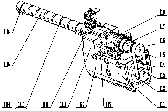
[0040] Such as image 3 and Figure 4As shown, the plasticizing part 11 includes a plasticizing platform 1111, a plasticizing moving base 1110 and a motor moving base 111, the plasticizing moving base 1110 i...


PUM


Abstract

The invention provides a graded storage injection molding machine. The injection molding machine comprises a barrel capable of plasticizing the materials, a molten material tube, a storage cylinder capable of storing the material in a grading manner, and an injection cylinder, wherein plungers are flexibly sleeved in the storage cylinder and the injection cylinder respectively and connected with an oil cylinder, and the molten material tube is respectively and sequentially communicated with a discharge end of the barrel, the storage cylinder and the injection cylinder from the top to the bottom; a three-way change-over valve is arranged on the connection part of the molten material tube and the injection cylinder, and the injection cylinder is connected with a spray nozzle by the three-way change-over valve. The molten material which is plasticized by the barrel is stored in the storage cylinder and the injection cylinder in a grading manner, so that the plasticizing performance and the exhaust performance of the material are reliably ensured, and the quality of the materials is stable; simultaneously the barrel can continuously provide the molten material, and the plasticizing process of the materials and the quick filling of the storage cylinder with the molten material can be simultaneously performed in the machine injection pressure retaining period, so as to prepare for injection of the molten material in the next period. The graded storage injection molding machine is high-efficient and energy-saving and low in failure rate.

Description

technical field [0001] The invention relates to an injection molding machine, more specifically, to a graded storage injection molding machine. Background technique [0002] At present, traditional injection molding machines rely on hydraulic motors to drive the screw to rotate, heat the material in the barrel, push it forward and plasticize it, and the plasticized molten material is continuously accumulated at the head of the barrel, and the screw and plastic The plasticizing motor backs up until the molten material reaches the set injection volume, then the plasticizing motor stops, and the screw and the plasticizing motor push the molten material forward in a straight line by the back pressure cylinder to realize the process of injecting the molten material into the mold. [0003] The traditional plasticizing injection mechanism has the following disadvantages: [0004] 1. High ineffective energy consumption. Plasticization is driven by a hydraulic motor to drive the sc...

Claims


Application Information

Patent Timeline
Patent Type & Authority Applications(China)
IPC IPC(8): B29C45/17B29C45/54
CPCB29C45/542B29C45/544B29C2045/1792
Inventor 张琳王德俊
Owner 广东福能精密机械有限公司
Why Eureka
Try Eureka