Electronic hydraulic braking system

A hydraulic braking, electronic technology, applied in the direction of brake, brake transmission, transportation and packaging, etc., to achieve the effect of high maintainability, compact structure, simple and compact

Inactive Publication Date: 2014-04-30
TONGJI UNIV
View PDF5 Cites 25 Cited by
  • Summary
  • Abstract
  • Description
  • Claims
  • Application Information

AI Technical Summary

Problems solved by technology

[0007] The purpose of the present invention is to provide an electronic hydraulic braking system, aiming at the defects of the existing electro-hydraulic composite braking sy

Method used


Image

  • Electronic hydraulic braking system
  • Electronic hydraulic braking system
  • Electronic hydraulic braking system

Examples


Embodiment Construction

[0030] In order to make the technical problems, technical solutions and beneficial effects solved by the present invention clearer, the present invention will be further described in detail below in conjunction with the accompanying drawings and embodiments.

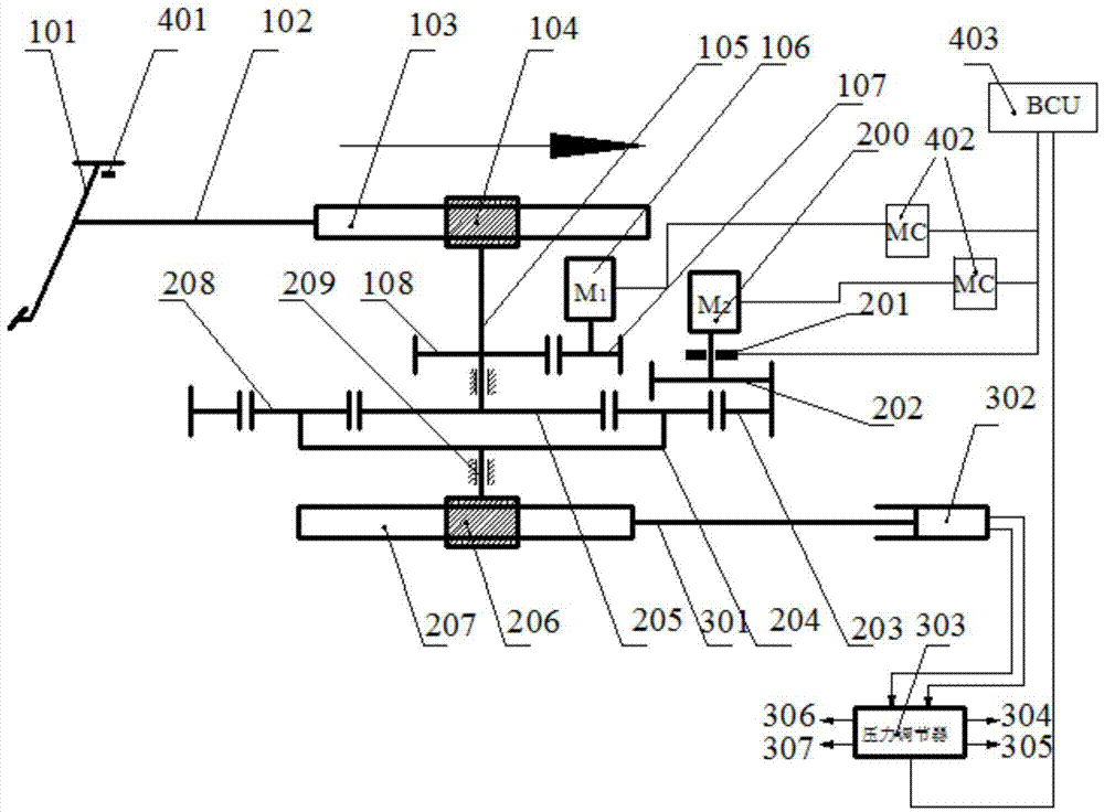
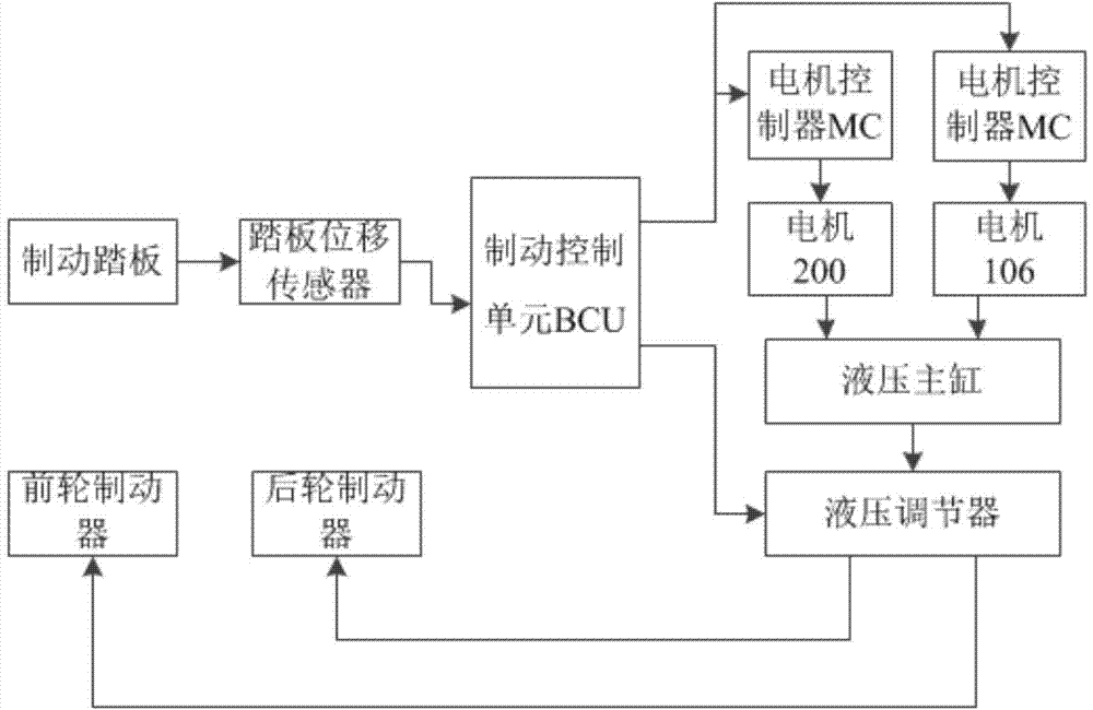
[0031] figure 1 It is a structural schematic diagram of an embodiment of the electronic hydraulic braking system according to the present invention. The electronic hydraulic braking system according to the present invention includes a brake pedal feeling simulation mechanism 1, an active pressure building pressure regulating mechanism 2, a brake actuator 3 and a braking mechanism. control system4.

[0032] In the described embodiment, the translation-rotation conversion mechanism in the brake pedal feeling simulation mechanism and the translation-transformation mechanism in the active pressure building and pressure regulation mechanism are all selected as a gear-rack transmission mechanism, and other such as screw thread...


PUM


Abstract

The invention belongs to the technical field of electric motor breaking, and relates to an electronic hydraulic braking system based on a planetary gear train. The electronic hydraulic braking system adopts dual motors to input, and comprises a brake pedal feeling simulation mechanism, an active pressure buildup and regulating mechanism, a brake actuator and a brake control system so as to simulate brake pedal feeling, actively regulate hydraulic braking force and perform failure protection. One motor is located in the brake pedal feeling simulation mechanism, and used for simulating the brake pedal feeling; the other motor is located in the pressure buildup and regulating mechanism, and used for active buildup and regulation control of hydraulic pressure; the active pressure buildup and regulating mechanism is a two-degree-of-freedom differential gear train mechanism with a locking mechanism. The system takes the motors as hydraulic pressure sources, has a failure protection function and is higher in reliability and safety, and a brake pedal feeling simulator does not need to be designed independently; meanwhile, the system has the advantages of simple and compact structure, easiness in control, complete functions, stable performance, low cost and higher maintainability.

Description

technical field [0001] The invention belongs to the technical field of automobiles, and relates to electronic hydraulic braking technology, in particular to an electronic hydraulic braking system which can actively adjust braking hydraulic pressure in good time and has the function of failure protection. Background technique [0002] With the intensification of the energy crisis, electric vehicles have become the development direction of a new generation of vehicles, and regenerative braking technology, as a key energy-saving technology for new energy vehicles, has received more and more attention. The regenerative braking technology enables the vehicle to convert a part of its braking energy into electric energy during the braking process, and store it in the energy storage device, so as to realize the energy reuse during braking and deceleration. [0003] The energy recovery method in the current regenerative braking technology of electric vehicles is realized by the rever...

Claims


Application Information

Patent Timeline
IPC IPC(8): B60T13/66B60T13/74
Inventor 熊璐袁兵徐松云余卓平
Owner TONGJI UNIV
Why Eureka
Try Eureka