Kitchen wastewater oil-water separation device

A technology of oil-water separation device and kitchen waste water, which is applied in the direction of liquid separation, separation method, grease/oily substance/floating matter removal device, etc. It can solve the problems of complex structure of oil-water separator, cumbersome and complicated gas source system, etc.

Active Publication Date: 2014-04-30
CHINA MACHINERY INT ENG DESIGN & RES INST
View PDF4 Cites 13 Cited by
  • Summary
  • Abstract
  • Description
  • Claims
  • Application Information

AI Technical Summary

Problems solved by technology

The structure of the existing oil-water separation device for oily wastewater is different due to the type or nature of the oil contained in the wastewater
[0004] Patent document No. 201120170867.3 discloses an "integrated automatic oil-water separator for catering wastewater". The body consists of a slag removal area, an air flotation area, an oil-water separation area and a water collection area in sequence; there is a filter basket in the slag removal area, a mechanical air flotation generator head in the air flotation area, and an oil collection tank and a chain in the upper part of the oil-water separation area. Type oil scraping device, the side plate of the oil collecting tank is an oil flow weir plate, through the chain type oil scraping device, the oil slick on the upper part of the oil-water separation area is scraped into the oil collecting tank; the upper part of the water collecting area has a water collecting tank, The water tank has a water outlet, and the side plate of the water collection tank is a water flow weir plate, which is used for catering waste water to go through the filter basket to remove food residues and then enter the air flotation area. The air flotation generator head impeller rotates at a high speed with a certain pressure of gas, and a large amount of water is generated accordingly. Micro-bubbles of 30-100 microns, the oil in the wastewater adheres to the micro-bubbles and floats up to achieve oil-water separation, which has a good effect; the disadvantages are: 1. Since the device uses air flotation method for oil-water separation, the air flotation generating device The operation needs to be equipped with a compressed gas source device and corresponding pipelines. The gas source system is cumbersome and complicated, and increases the cost; The installation of the oil de

Method used


Image

  • Kitchen wastewater oil-water separation device
  • Kitchen wastewater oil-water separation device
  • Kitchen wastewater oil-water separation device

Examples


Example Embodiment

[0052] See attached picture.

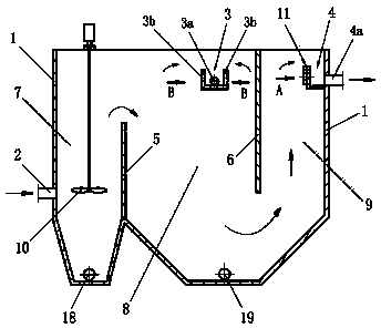
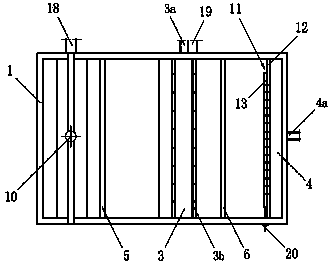
[0053] The present invention includes a shell 1, an oil collecting tank 3 and a water collecting tank 4. The shell 1 has an inlet pipe 2 on the wall, the oil collecting tank 3 has an oil outlet 3a, and the water collecting tank 4 has a water outlet 4a; the illustrated shell 1 is a cuboid structure.

[0054] The housing 1 is provided with a first vertical plate 5 and a second vertical plate 6, and a first oil-water separation area 7, a second oil-water separation area 8, and a water collection area 9 are sequentially formed in the housing 1; The upper part of the first oil-water separation zone 7 communicates with the upper part of the second oil-water separation zone 8, that is, the waste water channel; the lower part of the second oil-water separation zone 8 communicates with the lower part of the catchment zone 9, that is, the water flow channel;

[0055] The lower part of the first oil-water separation zone 7 has a lower cone structure, and a first ...


PUM


Abstract

The invention relates to a kitchen wastewater oil-water separation device. The shell is provided with a water inlet pipe; a first vertical plate (5) and a second vertical plate (6) are arranged in the shell to sequentially constitute a first oil-water separation region (7), a second oil-water separation region (8) and a water collection region (9); the upper part of the first oil-water separation region is communicated with the upper part of the second oil-water separation region; the lower part of the second oil-water separation region is communicated with the lower part of the water collection region; a stirring component (10) is arranged in the first oil-water separation region, an oil collection tank is arranged on the upper part of the second oil-water separation region, and the upper part of the water collection region is provided with a water collection tank; side plates of the water collection tank are weir plate components (11) capable of adjusting waterflow liquid level; mobile weir plates (13) in the weir plate components (11) can move horizontally along fixed weir plates (12); the mobile weir plates can be moved to adjust the waterflow liquid level; and a sloping plate component (17) is arranged in the second oil-water separation region. The kitchen wastewater oil-water separation device has primary and secondary oil-water separation, has the characteristics of simple structure and high operation stability, can lower the manufacturing cost and is convenient for maintenance and cleaning.

Description

technical field [0001] The invention relates to an oil-water separation device for oily wastewater, in particular to an oil-water separation device for high-concentration oily wastewater in the treatment of kitchen waste, and can also be used for oil-water separation of other types of oily wastewater. Background technique [0002] The oily wastewater produced during the treatment of kitchen waste is characterized by the fact that the oil is mainly animal and vegetable oils with high oil content, while the oily wastewater produced by industrial production processes such as metallurgy and mechanical processing is mostly mineral oil. [0003] Commonly used methods for oil-water separation include gravity method, centrifugation method, flotation method and so on. The structure of the existing oily wastewater oil-water separation device is different due to the different types or properties of the grease contained in the wastewater. [0004] Patent document No. 201120170867.3 dis...

Claims


Application Information

Patent Timeline
IPC IPC(8): C02F1/40
Inventor 蒋剑虹唐清畅罗友元王宏辉
Owner CHINA MACHINERY INT ENG DESIGN & RES INST
Why Eureka
Try Eureka