
Residual heat utilizing pusher furnace

A push rod type, waste heat technology, applied in heat treatment furnaces, furnaces, furnace types, etc., can solve the problems of large furnace body area, harsh operating environment, low energy utilization rate, etc., achieve ideal effects, shorten length, reduce The effect of a small footprint

Active Publication Date: 2015-06-24
NANJING CHANGJIANG IND FURNACE TECH GRP CO LTD
View PDF3 Cites 0 Cited by
  • Summary
  • Abstract
  • Description
  • Claims
  • Application Information

AI Technical Summary

Problems solved by technology

[0003] The purpose of the present invention is to provide a pusher type furnace with waste heat utilization, which solves the technical problems in the prior art that the furnace body occupies a large area, the material frame is difficult to return, the energy utilization rate is low, and the operating environment is harsh

Method used


Image

  • Residual heat utilizing pusher furnace
  • Residual heat utilizing pusher furnace
  • Residual heat utilizing pusher furnace

Examples


Embodiment Construction

[0018] The specific embodiments of the present invention will be further described below in conjunction with the accompanying drawings.

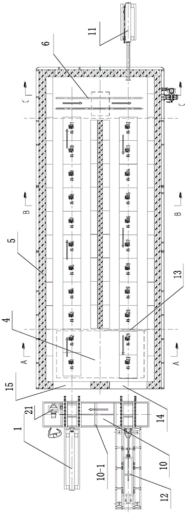
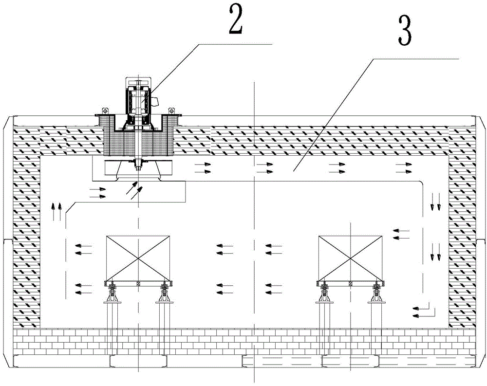
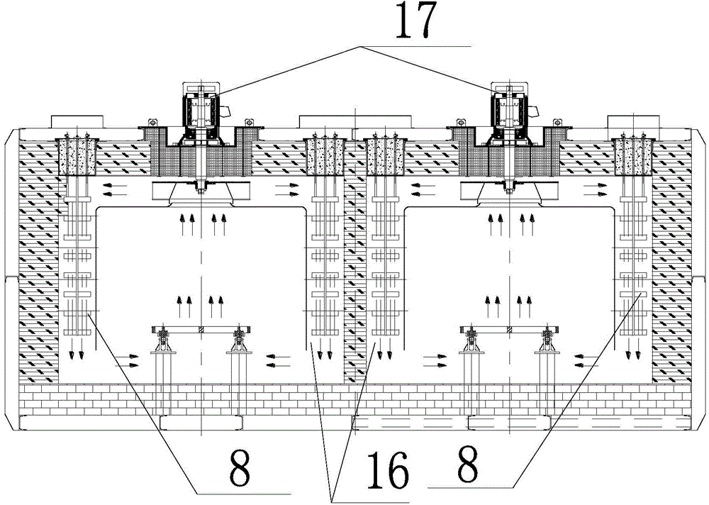
[0019] Such as Figure 1 to Figure 4 The shown push rod furnace with waste heat utilization includes a furnace body 5, the front end of the furnace body 5 is provided with a feed door 15 and a discharge door 14, and the front of the furnace body 5 is provided with an external translation device 10, and the furnace body 5 A preheating cooling chamber 4 is arranged in the front part, two parallel material passages are arranged in the middle along the direction of the length of the furnace body 5, and a translation passage in the furnace is arranged in the tail, and the preheating cooling chamber 4 and the translation passage in the furnace are respectively connected to two The front end and the rear end of the material passage, the conveying rollers are arranged in the preheating cooling chamber 4 and the material passage, the translation mech...


PUM


Abstract

The invention discloses a residual heat utilizing pusher furnace. The residual heat utilizing pusher furnace comprises a furnace body, wherein a feeding gate and a discharging gate are arranged at the front end of the furnace body, an out-of-furnace translation device is arranged in front of the furnace body, a pre-heating and cooling chamber is formed in the inner front part of the furnace body, two parallel material channels are arranged in the middle of the furnace body, an in-furnace translation channel is arranged at the tail part of the furnace body, the pre-heating and cooling chamber and the in-furnace translation channel are respectively communicated with the front ends and the rear ends of the two material channels, conveying rollers are arranged in the pre-heating and cooling chamber and the material channels, an in-furnace translation mechanism is arranged in the in-furnace translation channel, a front pusher and a discharging mechanism are arranged at the front end of the out-of-furnace translation device, a rear pusher is arranged at the rear of the furnace body, and a push rod of the pusher extends into the furnace body. The residual heat utilizing pusher furnace has the benefits that technical problems in the prior art, such as large occupying area of the furnace body, difficulty in material box return, low energy utilization rate and severe operating environments are effectively solved, experimental accounting shows that energy is saved by about 35% in comparison with the prior art, the structure is simple, and the operation is convenient.

Description

technical field [0001] The invention relates to a push rod type furnace with waste heat utilization, which belongs to the field of heat treatment technology. Background technique [0002] At present, most domestic push rod furnaces adopt a straight structure, that is, the input and output of the equipment are at both ends of the furnace body; the cooling chamber for the workpiece is generally installed at the output end to cool the workpiece, which is convenient for manual unloading. If it is necessary to send the material frame back to the feeding end, a set of material frame return mechanism is also required. Such a structure has many defects; for example: firstly, the equipment occupies a large area, and a separate material frame recovery mechanism needs to be installed next to the equipment; secondly, the temperature of the workpiece is relatively high (generally around 550°C), and the fan is used to cool it. A large amount of energy is taken away with the exhaust gas, ...

Claims


Application Information

Patent Timeline
Patent Type & Authority Patents(China)
IPC IPC(8): C21D9/00C21D1/00
Inventor 余德友
Owner NANJING CHANGJIANG IND FURNACE TECH GRP CO LTD
Learn More