Tube well used for unwatering and pressure-reducing drainage and drainage method of tube well

A technology for draining wells and relief wells, applied in construction and infrastructure engineering, etc., can solve problems such as difficulty in ensuring the sealing performance of water stopper devices, increasing construction complexity and difficulty, increasing construction costs, etc., to achieve improved The effect of soil dehydration and precipitation efficiency, high construction efficiency, and increasing catchment area

Active Publication Date: 2014-04-30
ZHONGYIFENG CONSTR GRP
View PDF7 Cites 10 Cited by
  • Summary
  • Abstract
  • Description
  • Claims
  • Application Information

AI Technical Summary

Problems solved by technology

In the dewatering and dewatering stage, the water-retaining plug realizes the function of water isolation to facilitate dewatering and dewatering, enters the decompression and dewatering stage, eliminates the water-isolation function of the water-retaining plug, and implements decompression and dewatering of the confined aquifer. The above utility model has the ability Reduce engineering costs, save resources, speed up construction progress, facilitate pit operations, and facilitate construction safety. However, due to the use of a water barrier device in the tube well, the water barrier device can be used to separate dewatering and decompression precipitation. However, since the sealing performance of the water stopper device is difficult to be guaranteed, it is necessary to conduct a watertight test on the

Method used


Image

  • Tube well used for unwatering and pressure-reducing drainage and drainage method of tube well
  • Tube well used for unwatering and pressure-reducing drainage and drainage method of tube well
  • Tube well used for unwatering and pressure-reducing drainage and drainage method of tube well

Examples


Embodiment 1

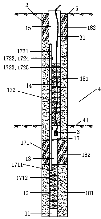
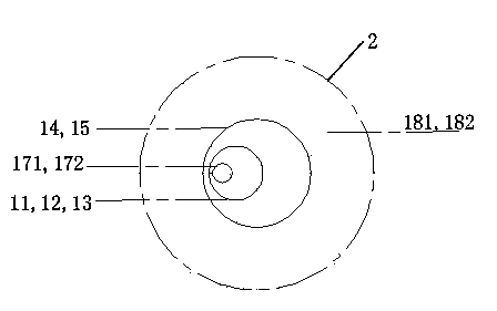
[0026] see Figure 1-Figure 4 , as shown in the illustration therein, a tube well for simultaneously dewatering and decompression dewatering includes a well tube, a hole 2 and a submersible pump 3, and the hole 2 is opened in the foundation pit 4.

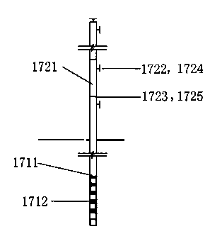
[0027]The above-mentioned well pipe includes a settling pipe 11, a decompression filter pipe 12, a decompression well wall pipe 13, a draining water filter pipe 14 and a draining well wall pipe which are sequentially arranged in the hole 2 from bottom to top. 15. A sealing plate 16 is installed at the junction of the decompression well wall pipe 13 and the draining and filtering pipe 14. An artesian pipe is installed on the sealing plate 16. The artesian pipe has an inlet pipe section 171 extending to the bottom of the sealing plate 16 and Extending to the water outlet pipe section 172 above the sealing plate 16, the water outlet pipe section 172 is sequentially arranged as eight socket pipes 1721 in the axial direction, and the ad...

Embodiment 2

[0042] The rest is the same as the first embodiment, the difference is that the above-mentioned eight upper water outlets are detachably connected to a corresponding partition plug, because only one partition plug is needed each time, thus reducing the number of partition plugs used , reducing the construction cost, and there will be no problems such as unnecessary plug loss.

Embodiment 3

[0044] The rest are the same as the first or second embodiment, the difference is that the inner diameter of the lower decompression well pipe is smaller than the inner diameter of the upper dewatering well pipe and is connected by a reducing pipe, and the above-mentioned sealing plate is installed on the above-mentioned reducing pipe. On the pipe, the above-mentioned reducer is a stepped reducer or a gradual reducer.


PUM


Abstract

The invention discloses a tube well used for unwatering and pressure-reducing drainage. The tube well comprises a well pipe comprising a precipitation tube, a pressure-reducing water filtering tube, a pressure-reducing well wall tube, an unwatering water filtering tube and an unwatering well wall tube which are sequentially arranged from bottom to top in a penetrating mode, and the joint of the pressure-reducing well wall tube and the unwatering water filtering tube forms a lower pressure-reducing well pipe and an upper unwatering well pipe through a seal board in a partitioning mode. The seal board is provided with a natural flow pipe comprising a water inlet pipe section and a water outlet pipe section, the water inlet pipe section is provided with a water inlet, the water outlet pipe section is sequentially provided with a plurality of water outlet pipe section bodies in the axial direction, each water outlet pipe section body is provided with a side wall water outlet and an upper water outlet, and the side wall water outlets and the upper water outlets are of opening and closing structures. The tube well simplifies drainage procedures, increases the drainage success probability, reduces engineering costs, accelerates the construction progress, increases the deep foundation pit excavation safety coefficient, and simplifies capping work. The invention further discloses a drainage method using the tube well.

Description

technical field [0001] The invention relates to a tube well for simultaneous dewatering and decompression dewatering, and in particular to a dewatering method for the tube well for simultaneous dewatering and decompression dewatering. Background technique [0002] At present, with the acceleration of urbanization and the rapid development of rail transit construction, large-scale deep foundation pit projects are increasing. Due to the existence of groundwater (diving, confined water), the excavation of foundation pits and underground constructions Construction often has adverse effects or constitutes a safety threat. It is necessary to use dewatering and dewatering (to make the working surface relatively dry) and decompression and dewatering (to eliminate the threat caused by the pressure of the pressurized water to the stability of the bottom of the foundation pit) to facilitate the operation in the pit. Especially to ensure the safety of the underground construction proces...

Claims


Application Information

Patent Timeline
IPC IPC(8): E02D19/10
Inventor 张楠韩树山
Owner ZHONGYIFENG CONSTR GRP
Why Eureka
Try Eureka