Heat recovery variable-frequency multi-split heat pump system and control method thereof

A heat pump system and heat recovery technology, applied in refrigerators, refrigeration components, refrigeration and liquefaction, etc., can solve the problems of high cost, complicated system piping and control, etc., to improve thermal comfort, increase cooling capacity and heating capacity , the effect of improving system efficiency

Active Publication Date: 2014-04-30
QINGDAO HISENSE HITACHI AIR CONDITIONING SYST
View PDF4 Cites 28 Cited by
  • Summary
  • Abstract
  • Description
  • Claims
  • Application Information

AI Technical Summary

Problems solved by technology

[0004] The purpose of the present invention is to provide a heat recovery frequency conversion multi-connection heat pump system, which solves the problem that the existing technology needs to use multiple four-way reversing valves to realize the heat recovery operation of the system, resulting in complex piping and control of the system and high cost. technical problem

Method used


Image

  • Heat recovery variable-frequency multi-split heat pump system and control method thereof
  • Heat recovery variable-frequency multi-split heat pump system and control method thereof
  • Heat recovery variable-frequency multi-split heat pump system and control method thereof

Examples


specific Embodiment 1

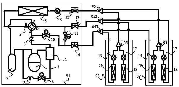
[0032] In this embodiment, two indoor units are taken as examples to specifically describe the implementation of the present invention:

[0033] Such as figure 2 As shown, the multi-connected heat pump system of this embodiment is composed of an outdoor unit 01 and two indoor units 02, 02'. Outdoor unit 01 includes: compressor 1, oil separator 2, one-way valve 3, four-way valve 4, outdoor heat exchanger 5, outdoor electronic expansion valve 6, gas-liquid separator 7, first solenoid valve 8, capillary tube 9 , the second solenoid valve 10, the third solenoid valve 11, the liquid side stop valve 12, the gas side stop valve 13 and the exhaust stop valve 14.

[0034]The first indoor unit 02 includes: a first indoor electronic expansion valve 15 , a first indoor heat exchanger 16 , a second indoor electronic expansion valve 17 , a second indoor heat exchanger 18 and a fourth branch pipe 05 . The components and configuration of the second indoor unit 02' are the same as those of ...

specific Embodiment 2

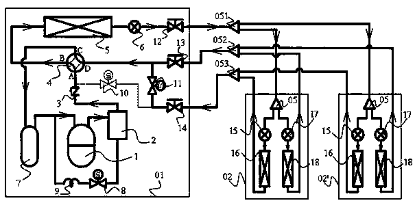
[0058] The multi-connected heat pump system of this embodiment is composed of an outdoor unit 01 and three indoor units 02, 02′, 02″. The outdoor unit includes two parallel inverter compressors. The pipelines of the indoor unit 02″ pass through branch pipes respectively 051', 052', 053' are connected to the pipeline of indoor unit 02'. The rest of the structures and implementation conditions are the same as those in Embodiment 1, and will not be repeated here.


PUM


Abstract

The invention relates to a heat recovery variable-frequency multi-split heat pump system and a control method of the heat recovery variable-frequency multi-split heat pump system. The system comprises an outdoor unit and two indoor units. According to the three-pipe heating recovery multi-split heat pump system designed based on a four-way reversing valve, each indoor unit is provided with two electronic expansion valves and two heat exchangers so that any indoor unit in the system can operate independently under the three working conditions of refrigeration, heating and heat recovery, and under the multi-split condition, the system has the function of operating under six working conditions, namely, the full-refrigeration working condition, the full-heating working condition, the common-heat-recovery working condition, the common-heat-recovery-dehumidification working condition, the heat recovery dehumidification and refrigeration combined working condition and the heat recovery dehumidification and heating combined working condition. Under the heat recovery dehumidification condition, heat emitted by a condenser is utilized for improving a low outlet air temperature during low-temperature dehumidification so as to achieve dehumidification without temperature fall or dehumidification with temperature rise, so that the thermal comfort and efficiency of the system are improved, and the refrigerating capacity and heating capacity of the system are effectively improved.

Description

technical field [0001] The invention belongs to the technical field of frequency conversion multi-connection heat pumps, and in particular relates to a heat recovery frequency conversion multi-connection heat pump system and a control method thereof. Background technique [0002] The frequency conversion multi-connected heat pump system is a complex refrigeration system with complex structure, huge system, highly coupled internal parameters, and various boundary conditions. An important direction for the development of air conditioning. like figure 1 As shown, the multi-connected heat pump system generally consists of one or more outdoor units 01, one or more indoor units 02, central control network (CS-NET) 03, refrigerant pipeline 04, branch pipe 05 and communication lines 06 components, multiple outdoor units form an outdoor unit, the central control network controls the outdoor unit through communication lines, and the outdoor unit is connected to the indoor unit throu...

Claims


Application Information

Patent Timeline
Patent Type & Authority Applications(China)
IPC IPC(8): F25B13/00F25B49/02
CPCF25B2313/007F25B2313/0231F25B2313/0233F25B2600/2515F25B13/00F25B43/02F25B2600/2513F25B41/26F25B41/34F25B41/20F25B41/385F25B2600/2501F25B2313/0232Y02B30/70
Inventor 刘敏王远鹏张文强曹锐李亚军李永梅
Owner QINGDAO HISENSE HITACHI AIR CONDITIONING SYST
Why Eureka
Try Eureka