
Error analysis method for measuring high-power microwave phase position through directional coupler

A directional coupler, high-power microwave technology, applied in measurement devices, measuring electrical variables, phase angle between voltage and current, etc., can solve problems such as errors, and achieve the effect of reducing errors

Inactive Publication Date: 2014-04-30
INST OF PLASMA PHYSICS CHINESE ACAD OF SCI
View PDF6 Cites 7 Cited by
  • Summary
  • Abstract
  • Description
  • Claims
  • Application Information

AI Technical Summary

Problems solved by technology

But in the TOKMAK low clutter system, the load is a changing plasma, and under this mismatch condition, there will be a certain error in the phase measurement

Method used


Image

  • Error analysis method for measuring high-power microwave phase position through directional coupler
  • Error analysis method for measuring high-power microwave phase position through directional coupler
  • Error analysis method for measuring high-power microwave phase position through directional coupler

Examples


Embodiment Construction

[0041] An error analysis method for measuring high-power microwave phase with a directional coupler, comprising the following steps:

[0042] (1) Signal analysis in the waveguide, according to the microwave transmission line theory, the relationship between the incident signal and the reflected signal is obtained from the analysis of the simplified signal flow diagram:

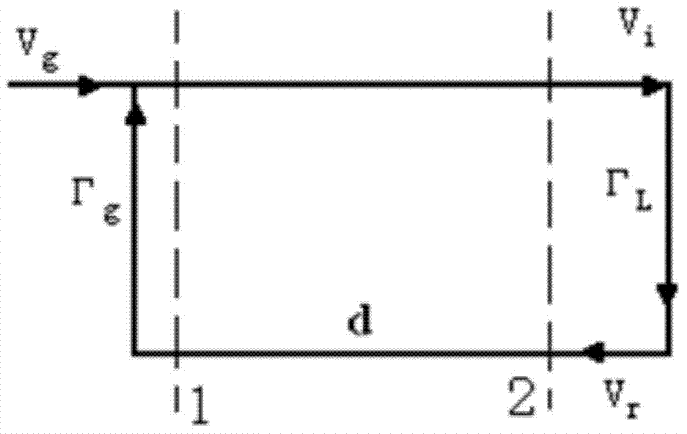
[0043] The signal flow diagram in the waveguide transmission line is as follows: figure 1 shown. The definition of each character is as follows: V g , V i , V r are the source voltage signal, the incident wave voltage signal and the reflected wave voltage signal at the waveguide port; Γ g is the source voltage reflection coefficient; Γ L is the load voltage reflection coefficient; d is the distance between the measuring port and the load; β is the propagation constant;

[0044] Such as figure 1As shown, the left side of dashed line 1 is equivalent to the signal viewed from the coupled port of the dire...


PUM


Abstract

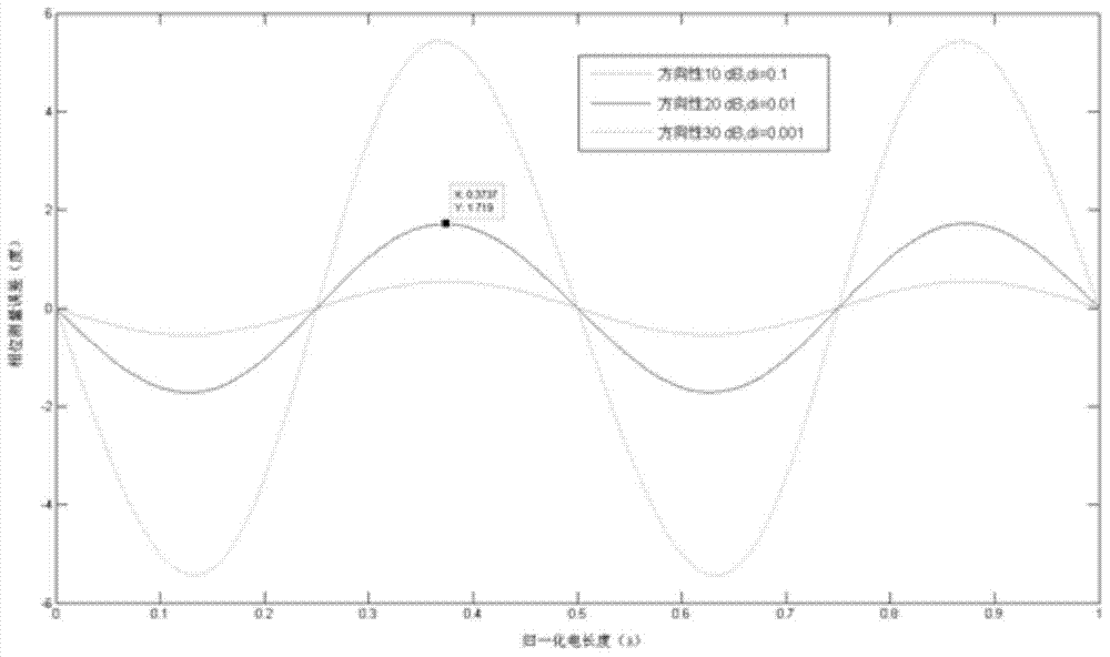
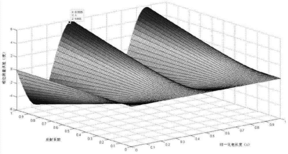
The invention discloses an error analysis method for measuring a high-power microwave phase position through a directional coupler. The method includes the first step of obtaining a relational expression between a measured phase position and an actual phase position through analysis of a simplified signal flow diagram according to the microwave transmission line theory, the second step of carrying out analytical calculation by means of programming according to the relational expression obtained in the first step to obtain a quantized phase error, and the third step of carrying out optimization on a hardware system through the direction of error analysis so as to reduce the error to the maximum degree. Through the method, the phase measurement error of a high-power microwave system of a TOKMAK device is analyzed to obtain factors influencing the phase measurement error; on the basis of analysis of the simplified signal flow diagram, the expression of the high-power microwave phase measurement error is obtained, the measurement error is analyzed through a calculation program according to the relational expression, and finally the relation between the phase measurement error and a directivity factor and the relation between the electrical length and a reflection coefficient are obtained.

Description

technical field [0001] The invention relates to the technical field of high-power microwave coupling measurement and data processing, in particular to an error analysis method for measuring high-power microwave phase by a directional coupler. Background technique [0002] On the EAST device of the National Science and Engineering Full Superconducting Tokamak, low clutter (LHW) is one of the very effective non-inductive current drive methods, that is, the use of high-power microwaves (MW order) to heat and drive plasma body. Different physical experiments have different requirements on the low clutter power spectrum, which determines that the low clutter system should flexibly control the phase difference between adjacent waveguides of the antenna. In the high-power microwave system, the signal in the waveguide is coupled by a directional coupler, and then sent to the phase detection system for comparison to obtain the phase difference between adjacent waveguides, and the ph...

Claims


Application Information

Patent Timeline
IPC IPC(8): G01R25/00
Inventor 王茂
Owner INST OF PLASMA PHYSICS CHINESE ACAD OF SCI
Learn More