

Resin curing device and method for curing photocurable resin
A light-curing resin and resin curing technology, applied in the direction of heating devices, drying solid materials, heating to dry solid materials, etc., can solve problems such as inability to adjust gloss
- Summary
- Abstract
- Description
- Claims
- Application Information
AI Technical Summary
Problems solved by technology
Method used
Image

Examples
Embodiment approach
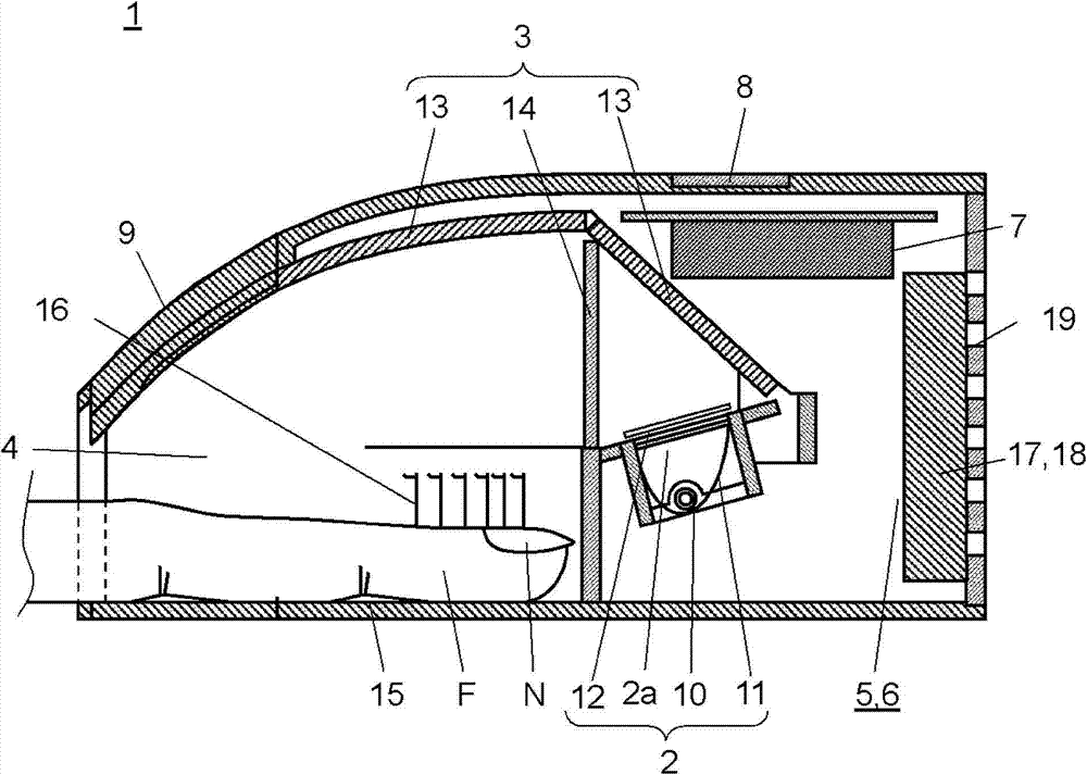
[0030] Below, refer to figure 1 , the resin curing device according to the embodiment of the present invention will be described.
[0031] Such as figure 1 As shown, the resin curing apparatus 1 of this embodiment is composed of at least a light emitting unit 2, an optical system 3, an irradiation chamber 4, a drying unit 5, a cooling unit 6, a control unit 7, an operation unit 8 and the like housed in a housing 9. The light emitting unit 2 emits irradiation light for curing a photocurable resin (not shown) such as gel applied on the nail N. As shown in FIG. The optical system 3 guides the irradiation light to the nail N coated with the photocurable resin. The irradiation chamber 4 is inserted to house the fingertip F to which the nail N is irradiated with irradiation light. The drying unit 5 dries the photocurable resin applied on the nail N. As shown in FIG. The cooling unit 6 cools the light emitting unit 2 . The control unit 7 controls the irradiation of the irradiati...
Embodiment 1
[0079] Based on Example 1, the resin curing device of this embodiment will be specifically described.
[0080] That is, refer to Figure 3A to Figure 5 , to describe the use of the resin curing device 1 of the present embodiment, taking general commercially available photocurable resin products as objects, with Figure 3A to Figure 3D The measurement result of the glossiness of the photocurable resin cured by the irradiation pattern described above.
[0081] Figure 4 and Figure 5 It is a figure which shows the measurement result of Example 1 of the resin curing apparatus of this embodiment.
[0082] First, the method of measuring the glossiness will be explained.
[0083] First, a color gel as a photocurable resin was applied to a blacked-out acrylic plate having a size of 25 mm×25 mm using a spacer having a thickness of 50 μm.
[0084] Next, enable the Speedlite 10 with Figure 3A to Figure 3D Each of the irradiation patterns shown irradiates and cures the color gel c...
Embodiment 2
[0105] Below, refer to Figure 3A to Figure 3D and Figure 6 , the result of measuring the glossiness of the photocurable resin in each irradiation pattern based on Example 2 will be specifically described with respect to the resin curing apparatus of the present embodiment.
[0106] Figure 6 It is a figure which shows the measurement result of Example 2 of the resin curing apparatus of this embodiment.
[0107] Example 2 The color gel and transparent gel, which are the photocurable resins of Example 1, were changed to a Pregel (registered trademark) 2way (pink) photocurable resin that is also used for UV-LED, and the glossiness of each irradiation pattern was measured. Figure 6 The measurement results of glossiness in Example 2 are shown. In addition, the measuring method of glossiness is the same as that of Example 1.
[0108] In addition, as a light source, a xenon discharge tube and a UV-LED having an emission interval fixed at 66 Hz were used. It should be noted th...
PUM
 Abstract
Description
Claims
Application Information