Eureka AIR delivers breakthrough ideas for toughest innovation challenges, trusted by R&D personnel around the world.

Graphite distribution collector

A collector and graphite technology, which is applied to the column field of a rectification tower, can solve the problems of short service life of the distribution collector, corrosion of the distribution collector, inability to aggregate and distribute, etc. coefficient, the effect of shortening the production cycle

Active Publication Date: 2014-05-07
WUXI YANGSHI CHEM
View PDF4 Cites 3 Cited by
  • Summary
  • Abstract
  • Description
  • Claims
  • Application Information

AI Technical Summary

Problems solved by technology

The existing distribution collectors are usually made of metal materials, such as stainless steel. In actual use, due to the acidity of the material and the penetration corrosion of chloride ions, the distribution collectors are often severely corroded and cannot be collected and distributed. The distribution collectors The service life is short, and it needs to be replaced at least 2~3 times a year, and the production needs to be stopped for 2~3 days for each replacement. The cost of one replacement is about 6,000 yuan, the maintenance cost is high, and the production efficiency is reduced.
In addition, in the existing distribution collector, although the distribution pipe is evenly distributed, after the liquid material overflows through the distribution pipe, the distribution point is single, or the distribution point is still uneven due to random overflow, and the mass and heat transfer efficiency is low. Low, the rectification efficiency is also low

Method used


Image

  • Graphite distribution collector
  • Graphite distribution collector
  • Graphite distribution collector

Examples


Embodiment Construction

[0020] The specific implementation manners of the present invention will be further described in detail below in conjunction with the accompanying drawings.

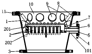
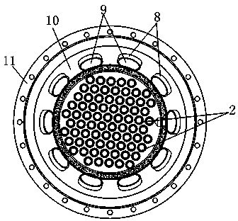
[0021] like Figure 1~5 As shown, the present invention includes a housing 1, the housing 1 is a truncated cone with a large top and a small bottom, and is made of stainless steel. The upper and lower ends of the housing 1 are respectively welded with a stainless steel upper connecting flange 11 and a lower connecting flange 3 , can be connected with the condenser through the upper connecting flange 11, and can be connected with the rectifying tower through the lower connecting flange 3. The collecting tray 7 is in the shape of a circular disc, and three fixing feet are welded on the inner wall of the housing 1, and the collecting tray 7 is horizontally fixed and installed in the housing 1 through the fixing feet. The side wall of the housing 1 is provided with a discharge sleeve 101, and the pipe end of the discharge s...


PUM


Abstract

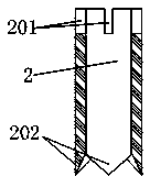
The invention relates to a graphite distribution collector. The graphite distribution collector is characterized by comprising a shell, wherein a collecting tray is fixedly arranged in the shell; a plurality of distribution pipes which vertically penetrate through the bottom surface of the collecting tray are uniformly arranged on the bottom surface of the collecting tray in an array form and are circular pipes; at least two overflow notches which are symmetrical to each other are formed in the upper end of each circular pipe; saw-toothed distribution teeth are arranged at the lower end of each distribution pipe; the number of the saw-toothed distribution teeth is equal to that of the overflow notches; the tooth tip of each distribution tooth and the corresponding overflow notch are positioned in the same vertical line. The graphite distribution collector is simple and compact in structure, low in manufacturing cost and maintenance cost, and convenient and quick to assemble and disassemble; a plurality of pairs of overflow notches and distribution points in the same vertical line are arranged on each distribution pipe; the number of the distribution points is increased, the distribution points are uniform, materials are uniformly distributed, coefficients of a tower plate are improved, the mass and heat transfer efficiency is improved, the rectification efficiency is improved, the production cycle is shortened, and the production efficiency is improved; the distribution pipes and the collecting tray are made of graphite and are corrosion-resistant, and the service life is prolonged.

Description

technical field [0001] The invention relates to a column device of a rectification tower, in particular to a graphite distribution collector. Background technique [0002] The distribution collector is a device used for distribution and collection of liquid materials for various purposes in the rectification of chemical, pharmaceutical and other fields. The existing distribution collectors are usually made of metal materials, such as stainless steel. In actual use, due to the acidity of the material and the penetration corrosion of chloride ions, the distribution collectors are often severely corroded and cannot be collected and distributed. The distribution collectors The service life is short, and it needs to be replaced at least 2 to 3 times a year, and the production needs to be stopped for 2 to 3 days for each replacement. The cost of one replacement is about 6,000 yuan, the maintenance cost is high, and the production efficiency is reduced. In addition, in the existin...

Claims


Application Information

Patent Timeline
Patent Type & Authority Applications(China)
IPC IPC(8): B01D3/14
Inventor 周康斌季演东钱云波
Owner WUXI YANGSHI CHEM
Why Eureka
Eureka Blog
Learn More