Automatic grating steel reinforcement cage welding device

An automatic welding and steel cage technology, applied in welding equipment, auxiliary welding equipment, welding/cutting auxiliary equipment, etc., can solve the problems of high labor intensity, low production efficiency, poor quality, etc., and achieve low labor intensity and high work efficiency , good quality effect

Active Publication Date: 2014-05-07
TJK MACHINERY TIANJIN
View PDF9 Cites 12 Cited by
  • Summary
  • Abstract
  • Description
  • Claims
  • Application Information

AI Technical Summary

Problems solved by technology

The prior art for preparing grid reinforcement cages has the defects

Method used


Image

  • Automatic grating steel reinforcement cage welding device
  • Automatic grating steel reinforcement cage welding device
  • Automatic grating steel reinforcement cage welding device

Examples


Embodiment Construction

[0022] The implementation of the present invention will be further described below in conjunction with the accompanying drawings.

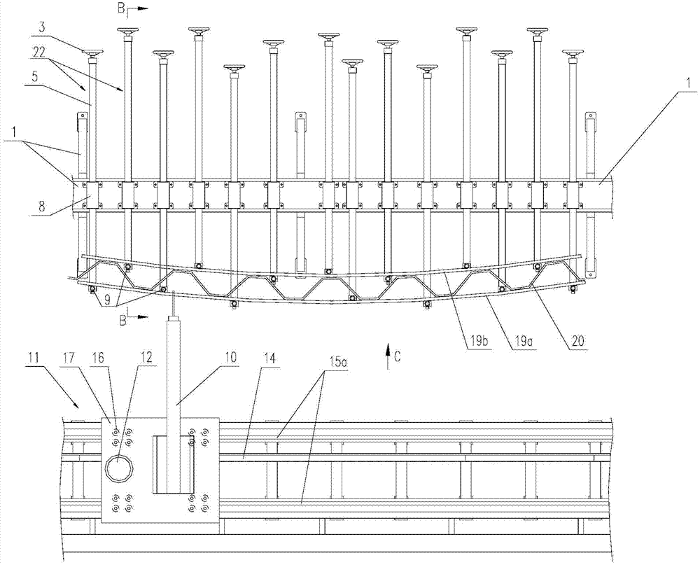
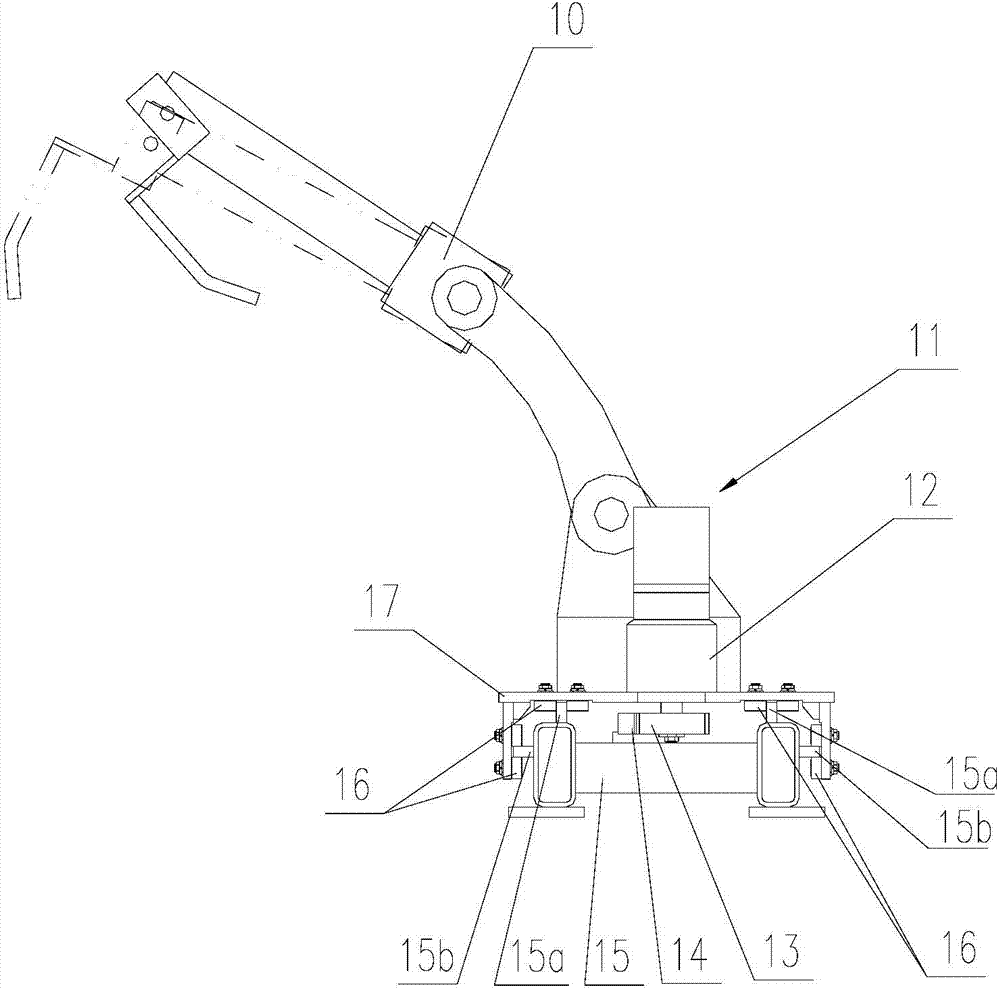
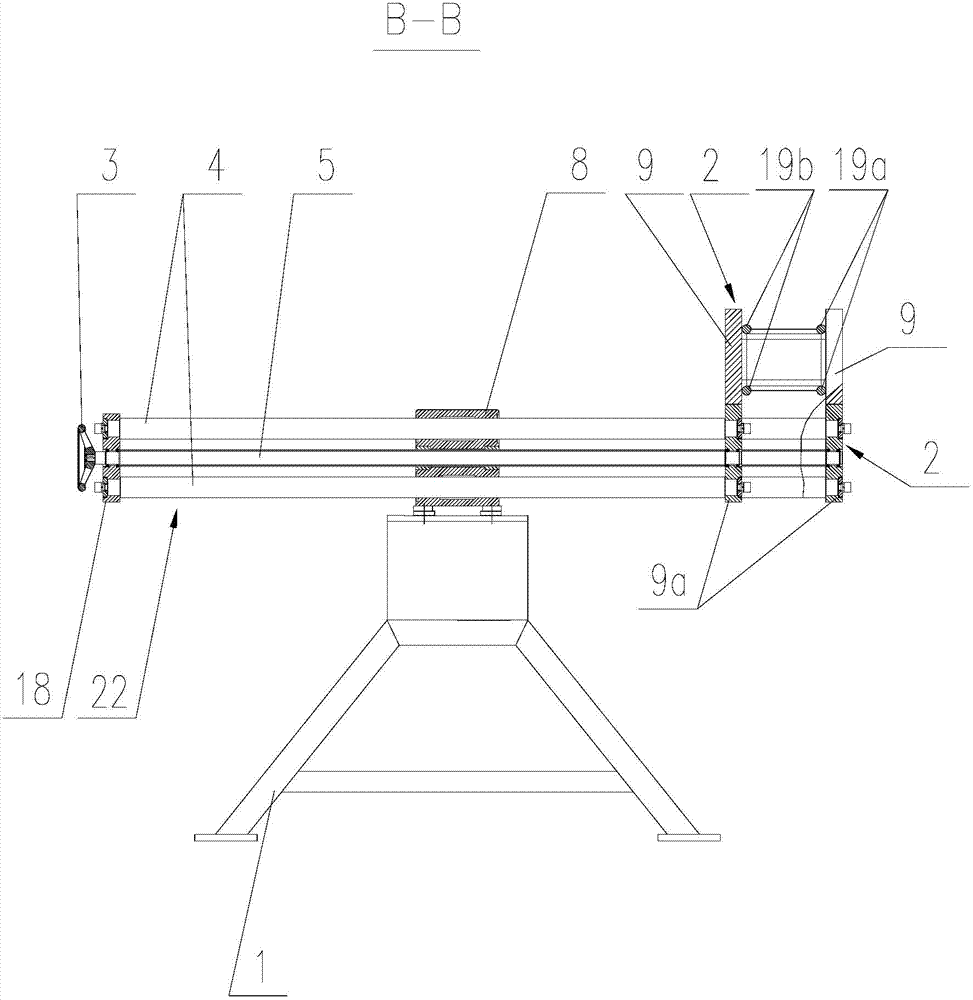
[0023] As shown in the figure, the present invention provides a kind of automatic welding equipment of grid reinforcement cage, and the automatic welding equipment of described grid reinforcement cage comprises: a plurality of welding adjustable clamps 2 with the same structure, and its structure all comprises: upper clamping The rod 9 and the upper clamping rod seat 9a connected to the bottom of the upper clamping rod 9; each upper clamping rod seat 9a is respectively connected with a reciprocating clamp adjustment device 22.

[0024] The upper clamping rods 9 of the plurality of welding adjustable fixtures 2 are respectively clamped on the arc edges on both sides of the outer arc main rib 19a and the arc edges on both sides of the inner arc main rib 19b of the grid steel cage 19; clamped on the two sides of the outer arc main rib 19a The adjacen...


PUM


Abstract

The invention discloses an automatic grating steel reinforcement cage welding device which comprises upper clamping rods, upper clamping rod bases connected to the bottom portions of the upper clamping rods, a welding robot and a robot travel driving device supporting the welding robot and driving the welding robot to movably weld a grating steel reinforcement cage along a plurality of adjustable welding clamps, wherein all the upper clamping rod bases are connected with a clamp adjusting device, and the upper clamping rods are clamped to the two lateral arched edges of an main outer arc reinforcement of the grating steel reinforcement cage and to two lateral arched edges of an main inner arc reinforcement of the grating steel reinforcement cage respectively. The device has the advantages that the adjustable welding clamps are connected with the clamp adjusting device, and as a result, welding of grating steel reinforcement cages in different lengths and specifications can be achieved, the using range is wide, and adjustability is high; the robot travel driving device is simple in structure, welding of the grating steel reinforcement cages can be achieved efficiently and quickly through the cooperation of the robot travel driving device and the welding robot, welding efficiency is high, and welding quality is good.

Description

technical field [0001] The invention relates to an automatic welding equipment for a grid reinforcement cage. Background technique [0002] During the construction of subways and tunnels, multiple arc-shaped grille reinforcement cages 19 are needed to provide a solid and safe space for subsequent projects. [0003] Figure 5 is a partial perspective view of the grid reinforcement cage; Figure 6 yes Figure 5 The front view of the middle grid reinforcement cage; Figure 7 yes Figure 5 Top view of the middle grid reinforcement cage. [0004] Such as Figure 5 to Figure 7 As shown, the grid reinforcement cage 19 includes two outer arc main ribs 19a arranged at intervals up and down and two inner arc main ribs 19b arranged at intervals up and down, the two outer arc main ribs 19a and the two inner arc main ribs 19b are respectively located In the vertical arc surface, the arc radius of the outer arc main rib 19a is greater than the arc radius of the inner arc main rib 19b;...

Claims


Application Information

Patent Timeline
IPC IPC(8): B23K37/00
CPCB21F31/00B23K37/0229B23K37/0247B23K37/0435
Inventor 陈振东
Owner TJK MACHINERY TIANJIN
Why Eureka
Try Eureka