

High accuracy frame for aircraft assembling tool and machining method thereof
A technology for assembling tooling and processing methods, applied in the field of machining, can solve the problems of multiple voids on the connecting surface, poor interchangeability, and difficult to repair, and achieve the effects of extending service life and reliability, easy transportation, and easy repair.
- Summary
- Abstract
- Description
- Claims
- Application Information
AI Technical Summary
Problems solved by technology
Method used
Image

Examples
Embodiment 1
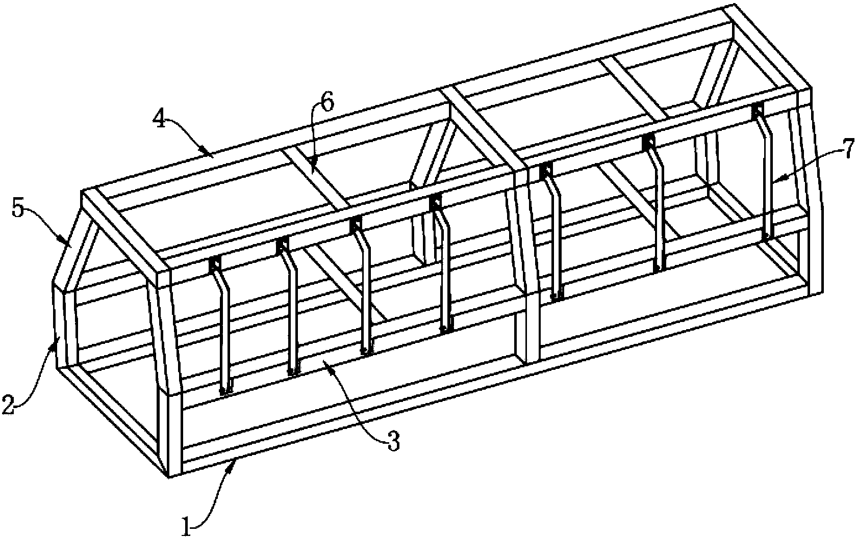
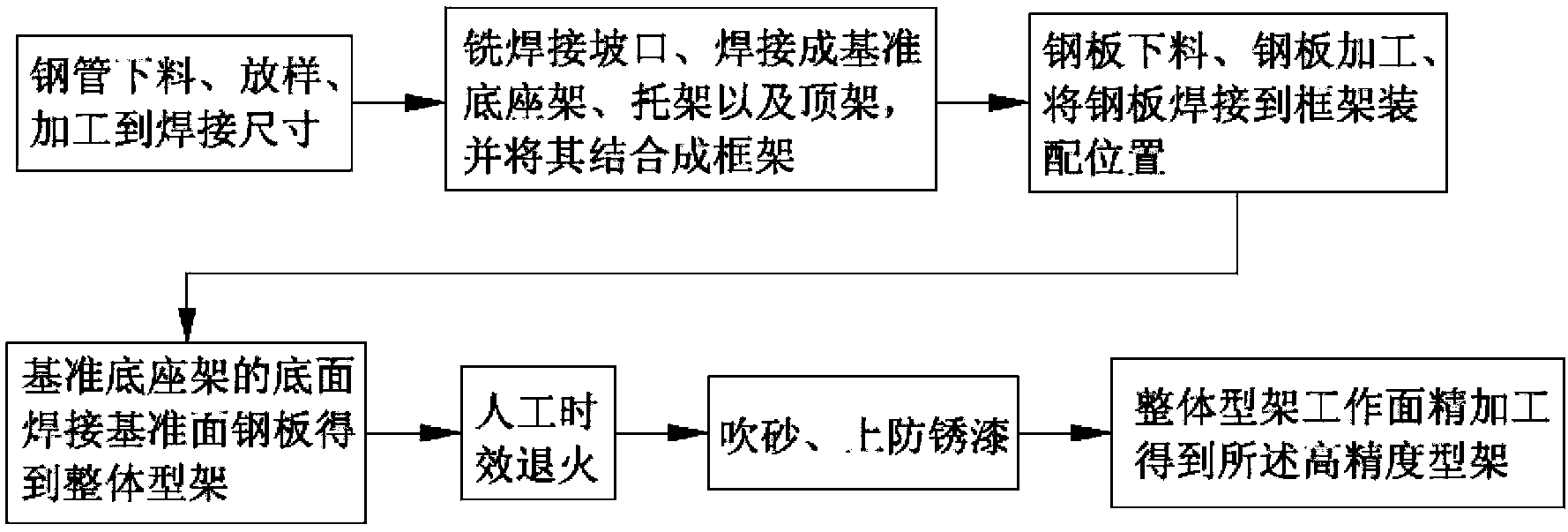
[0057] Embodiment 1, the processing method of the high-precision jig for large-scale helicopter assembly tooling, comprises the following steps, S1, steel pipe blanking, lofting, processing to welding size;
[0058] S2. Milling the welding groove, according to the groove of 30 degrees and 10mm from the periphery of the groove, that is, the angle of the groove is 30 degrees and the length is 10mm, which can ensure uniform welding seam and welding stress, so that all positions of the welding frame The deformation range and gap are reduced, and the strength and rigidity of the welded frame without groove are greatly improved; the base frame, bracket and top frame are welded and combined into a frame;
[0059] S3, steel plate blanking, steel plate processing, welding the steel plate to the frame assembly position;
[0060] S4. The bottom surface of the reference base frame is welded with a reference plane steel plate to obtain an integral frame;
[0061] S5. Artificial aging anne...
Embodiment 2
[0076] Embodiment 2, is used for the processing method of the high-precision type frame of small business aircraft assembly tooling, comprises the following steps, S1, steel pipe blanking, lofting, processing to welding size;
[0077] S2. Milling the welding groove, according to the groove of 30 degrees and 10mm from the periphery of the groove, that is, the angle of the groove is 30 degrees and the length is 10mm, which can ensure uniform welding seam and welding stress, so that all positions of the welding frame The deformation range and gap are reduced, and the strength and rigidity of the welded frame without groove are greatly improved; the base frame, bracket and top frame are welded and combined into a frame;
[0078] S3, steel plate blanking, steel plate processing, welding the steel plate to the frame assembly position;
[0079] S4. The bottom surface of the reference base frame is welded with a reference plane steel plate to obtain an integral frame;
[0080] S5. Ar...
PUM
 Abstract
Description
Claims
Application Information