Continuous type colored loose fiber machining device

A processing device and technology for dispersing fibers, applied in the field of continuous dispersive fiber processing devices, can solve the problems of long dyeing cycle, high cost, poor dyeing uniformity, etc., and achieve the effect of shortening the processing flow

Active Publication Date: 2014-05-07
绍兴国周针织科技有限公司
View PDF5 Cites 31 Cited by
  • Summary
  • Abstract
  • Description
  • Claims
  • Application Information

AI Technical Summary

Problems solved by technology

[0003] In order to overcome the defects of long dyeing cycle, poor dyeing uniformity, high energy consumption and high cost existing in the existing dispersion fiber processing tec

Method used


Image

  • Continuous type colored loose fiber machining device
  • Continuous type colored loose fiber machining device
  • Continuous type colored loose fiber machining device

Examples


Embodiment 1

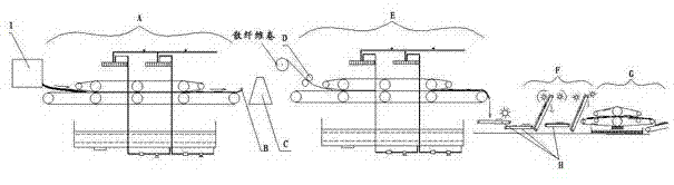
[0027] In this embodiment, the continuous fiber processing device with dispersion is combined with figure 1 , including the sequentially installed drenching pad dyeing machine A, coiling roll B, cold pile color fixing device C, cotton conveying roller D, drenching pad washing machine E, feeding belt H and water rolling device G, the loose fiber is in the drenching Spray dyeing is completed at the pad dyeing machine A, and the lapping roll B is installed behind the pad dyeing machine A, and the dyed loose fiber is rolled into a loose fiber roll, and the loose fiber roll is transferred to the cold pile color fixing device C After cold stacking and color fixing, the loose fiber rolls are transported to the rolling washing machine E through the cotton conveying roller D, and are sprayed and cleaned on the rolling washing machine E. The cleaned loose fibers are It falls on the feeding belt H behind the shower rolling washing machine E, and is sent to the water rolling device G thro...

Embodiment 2

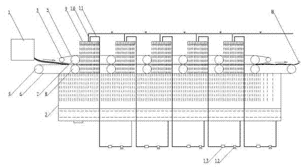
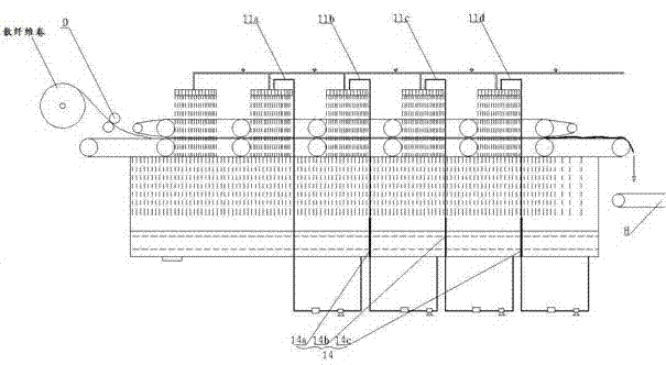
[0034] In this embodiment, circulation components are arranged below the lower guide belts of the shower pad dyeing machine A and the shower pad washing machine E. 13. According to the specific use situation, multiple return pipes 11 can be set to reuse the liquid in different areas to a suitable position, such as image 3 As shown in , in the structure of the pouring type water washing machine F, as the cleaning process proceeds, the dye liquor on the loose fiber gradually decreases, and when it reaches the last few upper rollers - lower rollers, the liquid squeezed out from the loose fiber It is still very clear, and it would be wasteful to discard it directly. Therefore, a partition 14 can be set in the sump at a position corresponding to the upper upper roll-lower roll, and a partition 14a and a partition 2 14b can be provided as required. And partition plate 3 14c, the liquid collection tank is divided into four independent areas, wherein, the first area is the area with ...

Embodiment 3

[0036] In this embodiment, an opening device F is arranged between the feeding belt H and the water rolling device G, and the opening device F includes a cotton stripper, a nail conveying curtain and a cotton opener, and the cotton stripper and the cotton opener are respectively located Before and after the nail conveying curtain, the cotton stripping beater will strip off the excess accumulated loose fiber to ensure the uniform supply of loose fiber on the nail conveying curtain; the nail conveying curtain and the cotton opening beater will loosen the loose fiber. In this embodiment , also can be set before the cotton stripping beater 16, be used for cake opening, the loose fiber group of bulk is broken into the loose fiber group of small piece; Groups are respectively cotton stripper one 17a, nail conveying curtain one 18a, cotton opening beater one 19a, cotton stripping beater two 17b, nail conveying curtain two 18b and cotton opening beater two 19b.

[0037] Feeding belt H...


PUM


Abstract

The invention relates to a continuous type colored loose fiber machining device, and belongs to the technical field of loose fiber dyeing. The continuous type colored loose fiber machining device comprises a spray-rolling type drying machine, a coiling roller, a cold-batch fixation device, cotton conveying rollers, a spray-rolling type washing machine, a conveyor belt and a squeezing device in sequence. Loose fibers are subjected to spraying dyeing by being horizontally clamped by a transmission component of the spray-rolling type drying machine, the coiling roller is arranged on the rear portion of a lower guide belt of the spray-rolling type drying machine and coils the dyed loose fibers to be loose fiber coils, the loose fiber coils are transferred to the cold-batch fixation device for cold-batch fixation, the loose fiber coils are conveyed to the spray-rolling type washing machine through the cotton conveying rollers, spray washing is carried out on the cotton conveying rollers when the cotton conveying rollers are conveyed by being horizontally clamped through the transmission component of the spray-rolling type washing machine, the washed loose fibers fall down on the conveyor belt behind the spray-rolling type washing machine under the gravity of the loose fibers themselves, and the loose fibers are conveyed to the squeezing device for dewatering. The continuous type colored loose fiber machining device can continuously produce colored loose fibers, and greatly lower processing cost.

Description

technical field [0001] The invention relates to a continuous fiber processing device with dispersion, which belongs to the technical field of loose fiber dyeing. Background technique [0002] The conventional processing process of dispersed fibers is as follows: first dye the loose fibers in the dyeing vat, hang out the dyeing vat after the dyeing is completed, perform multi-channel washing, soaping, hot water washing, etc., and then dry. The processing process is discontinuous. And there are a series of problems in this method. First, dyeing is carried out in the dyeing vat. In order to ensure the dyeing rate, it is necessary to add auxiliary dyeing accelerators and dyeing enhancers, which increases the dyeing cost and consumes a lot of energy and electricity. Moreover, the dyeing cycle is long and the dyeing uniformity is not good; secondly, multi-channel cleaning is required after dyeing, and the cleaning process consumes a lot of water. When necessary, soaping and hot wa...

Claims


Application Information

Patent Timeline
IPC IPC(8): D06B21/00D06B3/02D06B15/02D06B23/04D06B23/20
Inventor 金国周马国红杨征金小英莫冬根俞叶昌
Owner 绍兴国周针织科技有限公司
Why Eureka
Try Eureka