Valve system

A technology of reversing valve and main piston, applied in the field of valve system, can solve problems such as unpleasant running noise, and achieve the effects of low noise, stable quantity-displacement characteristic curve, and no impact on the quantity-displacement characteristic curve

Inactive Publication Date: 2014-05-07
ROBERT BOSCH GMBH
View PDF10 Cites 0 Cited by
  • Summary
  • Abstract
  • Description
  • Claims
  • Application Information

AI Technical Summary

Problems solved by technology

[0005] A disadvantage of such ballistic valves is that, when the valve opens, correspondingly hydraulic opening shocks are created which, due to the continuous repetition of the opening and closing movement or the stroke movement, generate a load on the connected hydraulic system via pressure peaks. and additionally produces unpleasant operating noises

Method used


Image

  • Valve system
  • Valve system
  • Valve system

Examples


Embodiment Construction

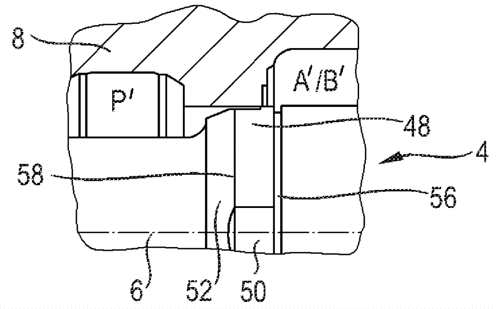
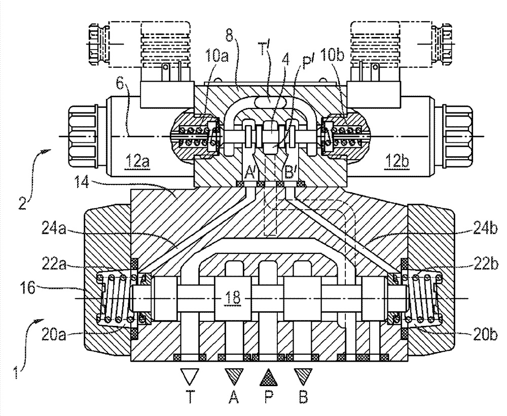
[0079] figure 1 A cross-sectional view of an embodiment of a pilot-controlled ballistic distribution directional valve of a valve system according to the invention is shown. The directional control valve has a main stage 1 and a pilot control stage or pilot stage 2 . The pilot stage 2 has a pilot control piston or pilot piston 4, which in the figure 1 is shown in its basic or closed position. The pilot piston 4 is displaceable in two directions along the longitudinal axis 6 . For this purpose, the pilot piston 4 is prestressed in its normal or closed position in the housing of the pilot control stage or the pilot housing 8 by means of two return springs 10a, 10b acting along the longitudinal axis 6 and can be moved by two The pilot magnets 12 a , 12 b are moved such that the pump connection P′ is connected either to the first control channel A′ of the pilot stage 2 or to the second control channel B′ of the pilot stage 2 . The respective further control channel A' or B' is...


PUM


Abstract

The valve device has a main stage (1) with a main piston (18), and control electronics through which shorter and longer electric pulses (26,28) can be generated by the main piston. An opening stroke with a short duration can be produced, due to the generation of electric pulses. The reversal position is spaced from an end position of the main piston. The main piston is designed such that a quantity-way characteristic of the switching-way valve is hop-free and steady.

Description

technical field [0001] The invention relates to a valve system according to the preamble of claim 1 . Background technique [0002] Proportional directional valves are known from the prior art, the valve body of which, in addition to a closed position and an open position, can also assume an intermediate position in which the flow cross section is only partially opened. It is thus possible to control the flow rate in such a directional control valve. A disadvantage lies in the installation technical complexity of such a directional control valve. [0003] An adjustable valve is known from laid-open document DE 10 2010 045 504 A1, the valve body of which can assume a switch-on position and can also be moved pulse-like or impact-like, whereby the valve is briefly opened. This opening movement or opening stroke is repeated several times. With this so-called ballistic mode, it is also possible to achieve a reduced throughflow compared to full opening, whereby a directly actua...

Claims


Application Information

Patent Timeline
Patent Type & Authority Applications(China)
IPC IPC(8): F15B13/043F15B21/08F16K31/06F16K47/02
CPCF15B13/0435F15B2211/328F15B2211/8606
Inventor A.科克曼S.舍勒J.菲舍尔S.海岑勒德
Owner ROBERT BOSCH GMBH
Why Eureka
Try Eureka