Integrated wall heat exchange device

A heat exchange device and an integrated technology, applied in the direction of fluid heaters, lighting and heating equipment, etc., can solve the problems of high discharge temperature of safety chimneys, affecting material hygiene and quality, discounting service life, etc., achieve compact structure, improve circling Speed, the effect of improving heat exchange efficiency

Active Publication Date: 2015-12-30
夏品荷
View PDF6 Cites 0 Cited by
  • Summary
  • Abstract
  • Description
  • Claims
  • Application Information

AI Technical Summary

Problems solved by technology

The open flame partition wall direct heating method is prone to scorching problems because the open flame temperature is too high; the boiler heating method will greatly reduce the service life
Regardless of the use of partitioned heat exchange or steam mixed heat exchange, the fact that scale will be produced in different degrees in the boiler, and the mixed heating material affects the hygiene and quality of the material, if the waste water (distilled water) generated by the partitioned processing material is not treated Utilization is also a waste, such as burning distilled wine, soy milk, etc., which are not easy to solve in the heat exchange processing of food, medicine and chemical industry
The technology related to the present invention is that the heat transfer oil is used as the heat storage medium. Because the heat storage temperature is high, the size of the heat exchange surface is not a problem, but there are safety and sanitation problems in the heat exchange materials on the partition wall and the high discharge temperature of the chimney; or the storage of materials The inner pot has or does not have a coil. As a result of heat exchange, relatively high-pressure steam is required to achieve heat exchange, which is not only time-consuming, but also energy-consuming.

Method used


Image

  • Integrated wall heat exchange device
  • Integrated wall heat exchange device
  • Integrated wall heat exchange device

Examples


Embodiment Construction

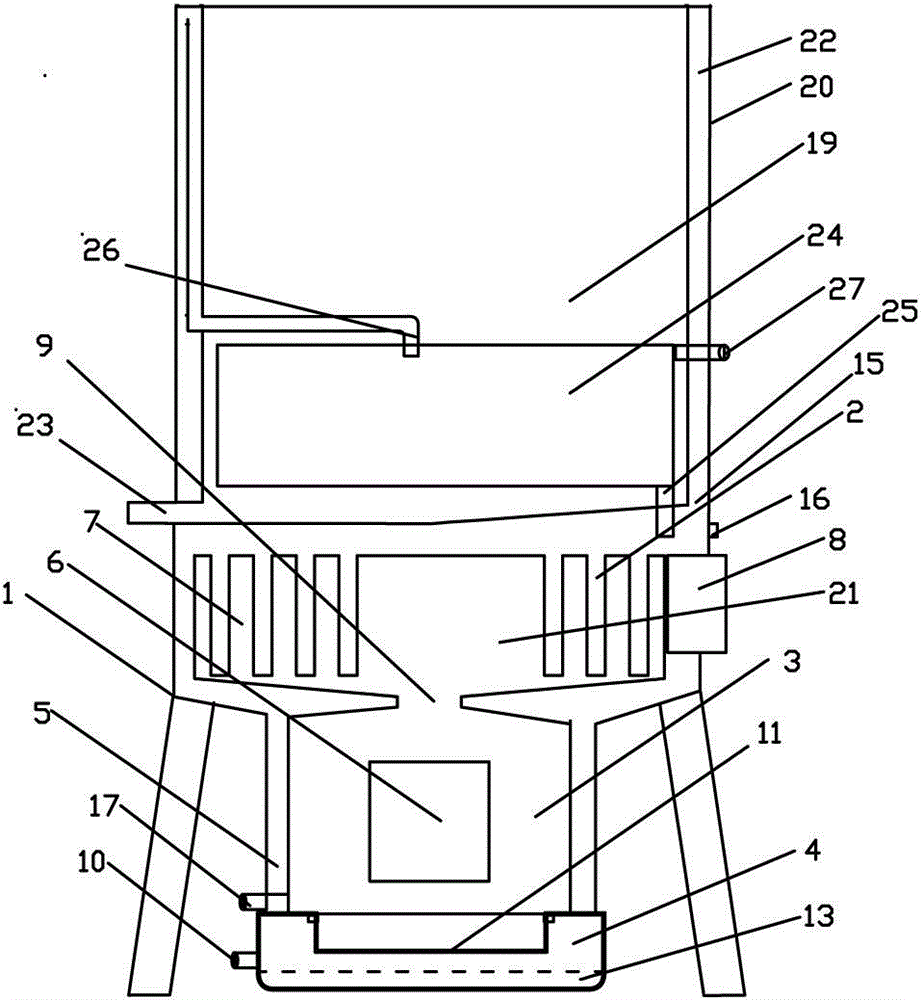
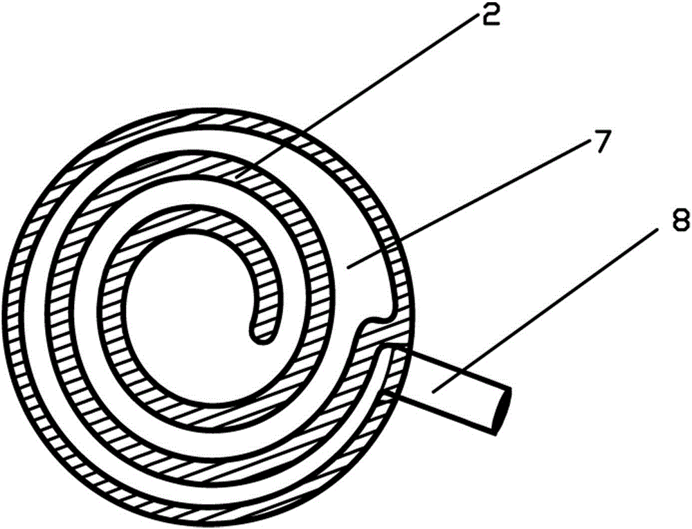
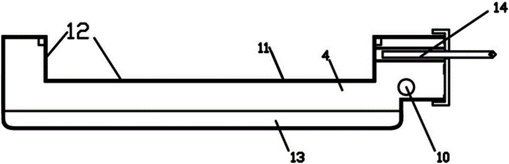
[0015] Such as figure 1 , figure 2 As shown, this embodiment is an integrated partition heat exchange device, which includes an inner pot body 19 with a material discharge port 23 at the bottom, an outer pot body 20 located outside the inner pot body, and a steam generator placed under the inner pot body twenty one. The outer pot body 2 is provided with a steam annular channel 22, the bottom of the inner pot body 19 is provided with a heat exchange member 24, the heat exchange member 24 is provided with a steam inlet 26 communicating with the outer pot body, and the lower part of the heat exchange member 24 is provided with a waste liquid discharge port 25. An air inlet and outlet 27 is provided on the upper part of the heat exchange component. The steam generating furnace includes a furnace body 1 , an inner container 2 with a single-channel spiral plate structure, a combustion chamber 3 located below the inner container 2 and an air inlet device 4 located below the combus...


PUM


Abstract

An integrated dividing wall heat exchanger comprises an inner pot body, an outer pot body and a steam generator, wherein the outer pot body is provided with a steam annular passage, the inner pot body is provided with a heat exchange component, the heat exchange component is provided with a steam inlet, the steam generator comprises a furnace body, an inner container with a single-channel spiral plate structure, a combustor and an air intake device, flue gas produced by the combustor enters from the center of the inner container and surrounds the external space of the inner container to form an annular spiral flue, water placed inside the inner container is heated to form steam, the produced steam enters the steam annular passage of the outer pot body, brushes the outer wall of the inner pot body from the top to the bottom and then enters the heat exchange component from the steam inlet of the heat exchange component to heat materials inside the inner pot body, and waste liquid produced after heat exchange of the heat exchange component enters the inner container of the steam generator from the waste liquid discharge opening for recycling. The integrated dividing wall heat exchanger has a compact entire structure, is high in heat exchange efficiency, water is not required to be added during heat exchange, and more functions of carrying out mixed type heat exchange on the materials by steam or supplying steam to the outside directly are integrated.

Description

technical field [0001] The invention relates to a partition heat exchange device. Background technique [0002] The heat exchange devices currently used in the market, such as cooking heat exchangers, are nothing more than direct heating with an open flame partition or mixing with materials, and heating materials with steam partitions or hybrids generated by boilers. The open flame partition wall direct heating method is prone to scorching problems because the open flame temperature is too high; the boiler heating method will greatly reduce the service life. Regardless of the use of partitioned heat exchange or steam mixed heat exchange, the fact that scale will be produced in different degrees in the boiler, and the mixed heating material affects the hygiene and quality of the material, if the waste water (distilled water) generated by the partitioned processing material is not treated Utilization is also a kind of waste, such as burning distilled wine, soybean milk, etc.,...

Claims


Application Information

Patent Timeline
Patent Type & Authority Patents(China)
IPC IPC(8): F24H9/18
Inventor 夏品荷
Owner 夏品荷
Why Eureka
Try Eureka