
System and method for measuring distribution of strong focused ultrasound nonlinearity sound fields

A non-linear sound field and strong focusing technology, applied in the measurement of ultrasonic/sonic/infrasonic waves, measuring devices, instruments, etc., can solve the problems of low accuracy of sound field measurement and insufficient bandwidth of the measurement system

Active Publication Date: 2014-05-07
NANJING UNIV
View PDF6 Cites 19 Cited by
  • Summary
  • Abstract
  • Description
  • Claims
  • Application Information

AI Technical Summary

Problems solved by technology

[0007] The purpose of the present invention is to overcome the existing high-intensity focused ultrasound non-linear sound field measurement method. The system and method for linear sound field distribution, the technical solution provided by the invention has high measurement accuracy and is easy to implement, and the sensitivity requirements of the hydrophone are relatively low in the measurement process, which avoids the inaccurate detection results caused by the low sensitivity of the hydrophone Hidden danger

Method used


Image

  • System and method for measuring distribution of strong focused ultrasound nonlinearity sound fields
  • System and method for measuring distribution of strong focused ultrasound nonlinearity sound fields
  • System and method for measuring distribution of strong focused ultrasound nonlinearity sound fields

Examples


Embodiment 1

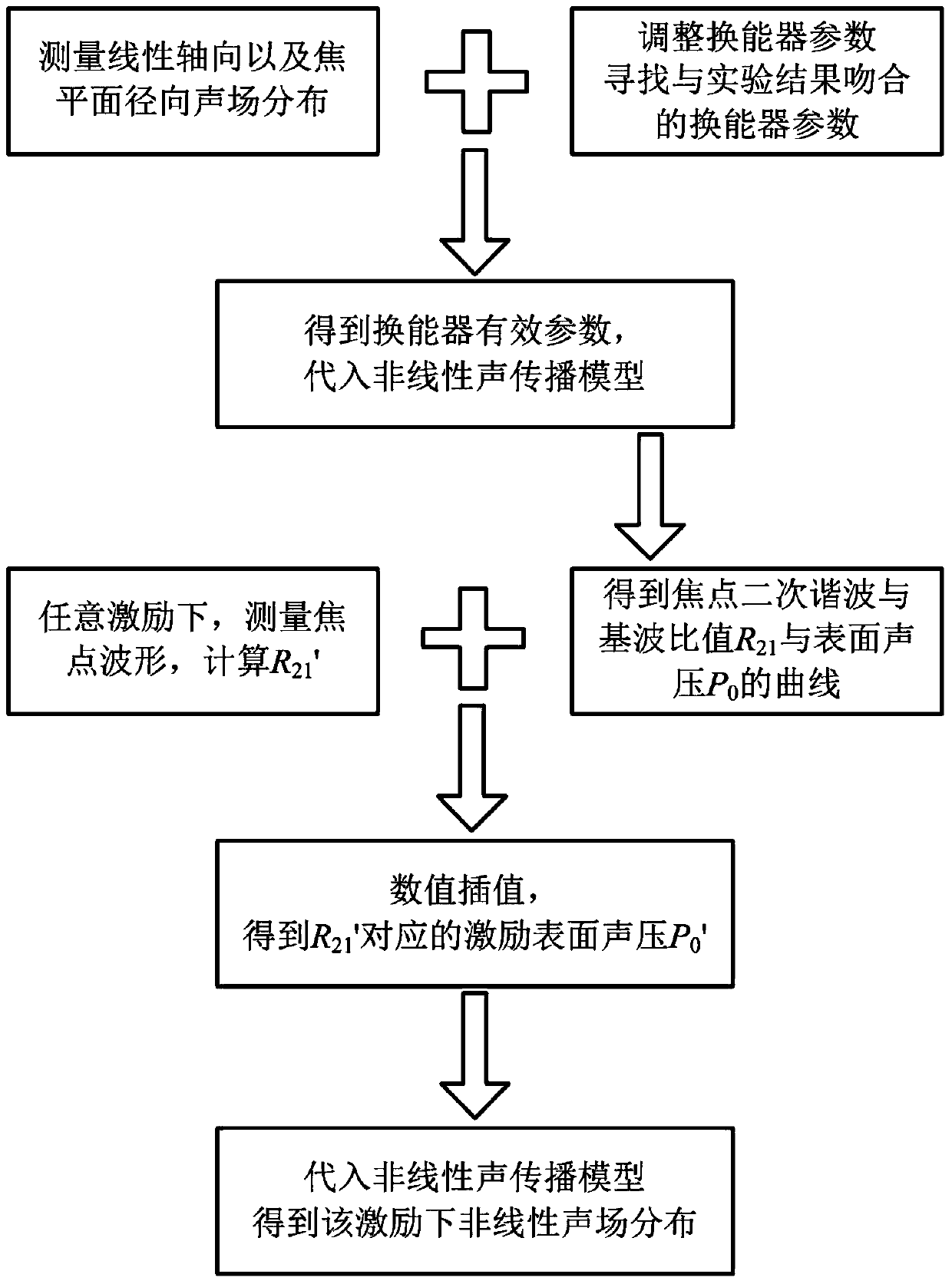
[0049] A method for measuring the nonlinear sound field distribution of intensely focused ultrasound in this embodiment (for the measurement process, see figure 1 ), the measurement steps are:

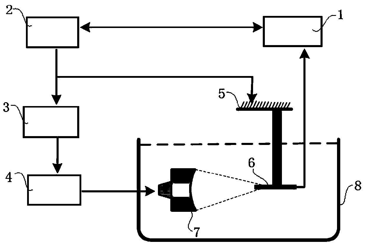
[0050] Step 1: Apply low-energy excitation to the spherical shell transducer 7, so that the amplitude of the second harmonic at the focal point is at least 40dB lower than the amplitude of the fundamental wave. Non-linear effects, which treat the sound field as a linear sound field. Fix the spherical shell transducer 7 in the water tank 8, control the three-dimensional motion platform 5 to drive the hydrophone 6 to measure the axial direction of the spherical shell transducer 7 and the focal plane of the spherical shell transducer 7 (the focal plane refers to the vertical The sound pressure distribution curve in the axial direction of the spherical shell transducer 7 and in the radial direction of the focal plane is obtained from the radial sound pressure on the symmetric axis of the ...


PUM


Abstract

The invention discloses a system and method for measuring distribution of strong focused ultrasound nonlinearity sound fields, and belongs to the technical field of ultrasound field measurement. The method comprises the steps that firstly, a distribution curve of the sound pressure in the axial direction of a spherical shell energy converter and a distribution curve of the sound pressure in the radial direction of a focal plane of the spherical shell energy converter are obtained; secondly, the sound pressure distribution curve in the axial direction of the spherical shell energy converter and the sound pressure distribution curve in the radial direction of the focal plane are calculated according to the Rayleigh integral, and the calculating result is compared with the measuring result to obtain a valid parameter; thirdly, the valid parameter is substituted into a nonlinearity sound propagation model to calculate R21, the P0 values are changed, R21 corresponding to different P0 values is calculated, and then the relation curve of R21 and P0 is obtained; fourthly, excitation is exerted on the spherical shell energy converter, the focus waveform is measured to be calculated to obtain R21', and P0' corresponding to R21' is obtained through interpolation; fifthly, P0' is substituted into the nonlinearity sound propagation model, and then the distribution of the nonlinearity sound fields is obtained. The system and method effectively solve the problem that the bandwidth of a hydrophone is insufficient when the hydrophone is used for measuring the nonlinearity sound fields, the relative value R21 serves as a judgment basis, and measuring hidden danger caused by not high sensitivity of the hydrophone is eliminated.

Description

technical field [0001] The invention relates to the technical field of ultrasonic sound field measurement, in particular to a system and method for measuring the distribution of an intensely focused ultrasonic nonlinear sound field. Background technique [0002] In the past ten years, high-intensity focused ultrasound (HIFU), as an emerging non-invasive method for treating tumors, has received great attention. The main principle of HIFU treatment of tumors is to focus the external ultrasound energy on the tumor tissue in vivo, the target tissue absorbs the acoustic energy, the temperature rises above 65°C in a short time, and irreversible coagulation necrosis occurs. To ensure the safety and effectiveness of treatment, the HIFU sound field distribution must be accurately described before treatment. Due to the high sound energy during HIFU treatment, the focal sound pressure can even reach the order of 100 MPa; strong nonlinearity leads to severe distortion of the sound wave...

Claims


Application Information

Patent Timeline
IPC IPC(8): G01H9/00
Inventor 范庭波陈涛章东胡济民张崴
Owner NANJING UNIV
Learn More