Lining viscosity measurement instrument

A measuring instrument and viscosity technology, applied in measuring devices, instruments, scientific instruments, etc., can solve the problems of unsuitable viscosity measurement of inner wall lining of pipelines, unsuitable for lining viscosity measurement, inaccurate positioning of viscometers, etc., and achieve a simple structure. , fast measurement, low maintenance cost

Inactive Publication Date: 2014-05-07
HUZHOU TEACHERS COLLEGE
View PDF10 Cites 18 Cited by
  • Summary
  • Abstract
  • Description
  • Claims
  • Application Information

AI Technical Summary

Problems solved by technology

[0002] At present, there are many relatively mature methods for the quantitative measurement of viscosity, such as capillary method, rotation method and vibration method, etc. There are also many types of viscometers that have been developed based on these methods, but most of them are only applicable to The quantitative measurement of fluid viscosity or the actuator is not suitable for the measurement of the viscosity of the inner wall of the pipeline. For example, the Chinese patent No. 200810041858.7 published on February 24, 2010 proposes a fluid rheological characteristics and viscosity measuring instrument , which includes: a mounting plate; a central connection mechanism is placed on the mounting plate; below the mounting plate and on the central connection mechanism are jewel bearing mechanisms and rotors in turn; it is characterized in that it also includes: above the mounting plate, The central connection mechanism is followed by a torque sensor, a torque displacement adjustment mechanism and a bearing mechanism; the bearing mechanism is connected to a stepping motor driven by a high-resolution stepping motor drive circuit; a Non-contact photoelectric sensor connected with computer processor control system
The invention patent with the Chinese patent number 201010114039.8 published on August 4, 2010 proposes an instrument that can accurately measure the viscosity of a fluid. There is a problem of inaccurate positioning of the upper and lower measuring positions of the viscometer
Although these inventions can realize the viscosity measurement of the fluid and can achieve a certain accuracy, they are not suitable for the measurement of the viscosity of the lining layer on the inner wall of the pipeline in engineering.

Method used


Image

  • Lining viscosity measurement instrument
  • Lining viscosity measurement instrument
  • Lining viscosity measurement instrument

Examples


Embodiment 1

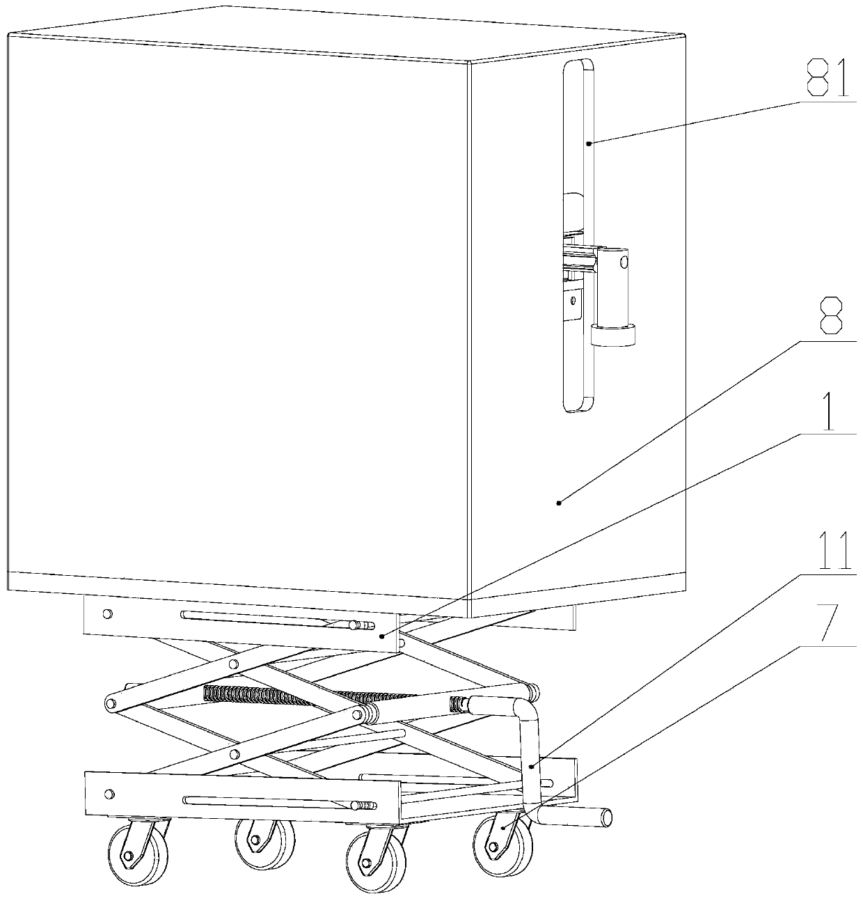
[0026] Such as figure 1 As shown, each transmission mechanism of the lining viscosity measuring instrument is in the box body 8, and each transmission mechanism includes a light guide rod 3, a ball screw nut pair 4, a platform 5, a first motor 21, and the like. Casing 8 is fixed on the scissor lift platform 1, and the scissor lift platform can be selected as the manually controlled lift platform of 200*200*280 produced by Beijing Zhongxing Company. The lifting of scissor lift table 1 adopts handle 11 hand control, and universal wheel 7 is equipped with at the bottom. The shell of casing 8 has a vertical groove 81, and pressure head 54 can move up and down, left and right, and linear guide rail 53 passes groove 81, and pressure head 54 is positioned at outside casing 8.

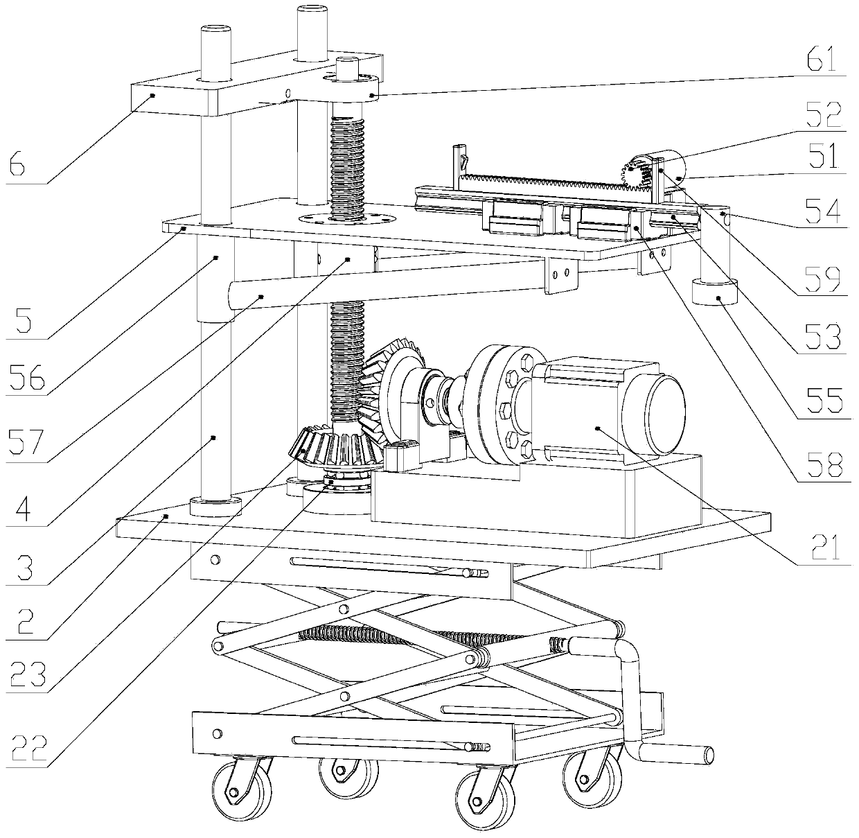
[0027] Such as figure 2 As shown, the top of the scissor lift table 1 has a bottom plate 2 on which two light guide rods 3 and one ball screw nut pair 4 are vertically arranged, and a fixed block 6 is arran...


PUM


Abstract

The invention relates to a lining viscosity measurement instrument which is provided with a shear type lifting table (1), wherein a bottom plate (2) is arranged at the top of the shear type lifting table (1); a guide light rod (3) and a ball screw nut pair (4) are arranged on the bottom plate (2); a platform (5) is arranged above the bottom plate (2) and is driven by the ball screw nut pair (4) to move up or down; power of the ball screw nut pair (4) is provided by a first motor (21) mounted on the bottom plate (2); a second motor (51), a gear rack mechanism (52) and a linear guide rail (53) are mounted on the platform (5); a pressing head (54) is mounted at the end part of the linear guide rail (53); a sensor (55) is arranged on the pressing head (54) and connected with a controller and a display; the gear rack mechanism (52) is driven by the second motor (51) to push the linear guide rail (53) to horizontally move. According to the device, the lining viscosity can be quickly measured.

Description

technical field [0001] The invention relates to a viscosity measuring instrument, in particular to a lining viscosity measuring instrument. Background technique [0002] At present, there are many relatively mature methods for the quantitative measurement of viscosity, such as capillary method, rotation method and vibration method, etc. There are also many types of viscometers that have been developed based on these methods, but most of them are only applicable to The quantitative measurement of fluid viscosity or the actuator is not suitable for the measurement of the viscosity of the inner wall of the pipeline. For example, the Chinese patent No. 200810041858.7 published on February 24, 2010 proposes a fluid rheological characteristics and viscosity measuring instrument , which includes: a mounting plate; a central connection mechanism is placed on the mounting plate; below the mounting plate and on the central connection mechanism are jewel bearing mechanisms and rotors i...

Claims


Application Information

Patent Timeline
Patent Type & Authority Applications(China)
IPC IPC(8): G01N11/00
Inventor 郑玉卿崔靖渝许海燕许虹怡
Owner HUZHOU TEACHERS COLLEGE
Why Eureka
Try Eureka