Fiber current sensor

A fiber optic current and sensor technology, applied in voltage/current isolation, measurement using digital measurement technology, etc., can solve the problems of reducing the modulation speed, inaccurate measurement accuracy, unfavorable fiber optic current sensor current measurement engineering, etc., to shorten the length. Effect

Active Publication Date: 2014-05-07
STATE GRID CORP OF CHINA +1
View PDF8 Cites 24 Cited by
  • Summary
  • Abstract
  • Description
  • Claims
  • Application Information

AI Technical Summary

Problems solved by technology

Although the fiber optic current sensor has the advantages of reducing the modulation speed, not needing to align the polarization axis during welding, and greatly reducing the technical difficulty of the active modulation scheme of the interferometric fiber optic current sensor

Method used


Image

  • Fiber current sensor
  • Fiber current sensor
  • Fiber current sensor

Examples


Embodiment Construction

[0026] The reflective Sagnac fiber optic current sensor of the present invention will be further described in detail below in conjunction with the accompanying drawings.

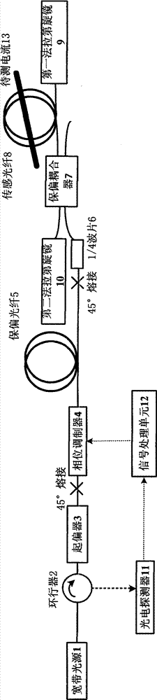
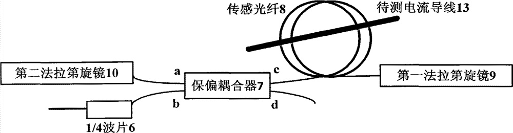
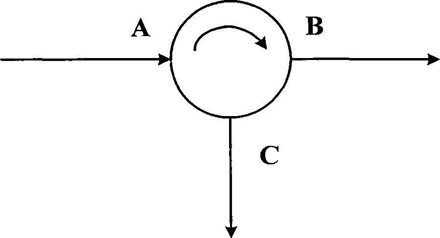
[0027] like figure 1 As shown, the fiber optic current sensor in this example includes a light source 1 (a broadband light source is used in this example), an optical circulator 2, a fiber polarizer 3, an optical phase modulator 4, a polarization-maintaining fiber 5, and a quarter-wave plate 6 , a polarization-maintaining coupler 7 (the splitting ratio selected in this example is 10:90), a sensing fiber 8, a current wire 13 to be measured, a first Faraday rotating mirror 9, a second Faraday rotating mirror 10, a photodetector 11 and Signal processing unit 12.

[0028] The working principle of the optical fiber current sensor is: the light emitted by the broadband light source SLD1 is transmitted to the optical fiber polarizer 3 through the optical circulator 2 and then becomes linearly polarized light, and ...


PUM


Abstract

The invention brings forward a fiber current sensor. The fiber current sensor comprises an optical path unit and an FP cavity which are connected through a polarization maintaining fiber. A quarter wave-plate is connected between the polarization-maintaining fiber and the FP cavity; the optical path unit comprises a light source, an optical circulator, a fiber polarizer and an optical phase modulator which are successively connected; the optical circulator is also connected with a signal processing unit through a photoelectric detector; the FP cavity comprises a polarization-maintaining coupler, a first Faraday rotating mirror, a second Faraday rotating mirror, and a sensing fiber for connecting with a current lead to be detected; one end of the sensing fiber is connected with the first Faraday rotating mirror; the other end of the sensing fiber is connected with one port at one side of the polarization-maintaining coupler; and two ports at the other side of the polarization-maintaining coupler are respectively connected with the second Faraday rotating mirror and the quarter wave-plate. The sensor provided by the invention can improve the precision of current measurement, especially for the measurement of low currents, so that a feasible method is provided for current measuring engineering of the fiber current sensor.

Description

technical field [0001] The invention belongs to the field of optical fiber current sensors, in particular to a reflective Sagnac type optical fiber current sensor based on polarization interference and a Faraday rotation mirror FP cavity. Background technique [0002] Current is the basic parameter of power system, and current sensor is an important device for measuring current. For a long time, electromagnetic induction current sensors have played a key role in current metering, power distribution, relay protection, control box monitoring, etc. in power systems. With the improvement of relay protection, electrical equipment automation and power system insulation level, the traditional current sensor based on electromagnetic induction has been unable to solve the problems due to its insulation, magnetic saturation and electromagnetic interference, small dynamic range, and difficult transportation and installation. Meet the needs of the growing power system. Aiming at these...

Claims


Application Information

Patent Timeline
IPC IPC(8): G01R19/25G01R15/24
Inventor 陈硕陈开鑫刘占元温海燕
Owner STATE GRID CORP OF CHINA
Why Eureka
Try Eureka