Cable conductor DC-resistance testing device and testing method

A technology for DC resistance testing and cable conductors, which is applied to measuring devices, measuring resistance/reactance/impedance, and measuring electrical variables, etc. It can solve the problems of poor repeatability, difficulty in maintaining consistency, and volatility of conductor resistance testing, and avoid test data. Inauthentic, save material waste cost, overcome the effect of large detection error

Active Publication Date: 2014-05-07
FAR EAST CABLE +2
View PDF5 Cites 17 Cited by
  • Summary
  • Abstract
  • Description
  • Claims
  • Application Information

AI Technical Summary

Problems solved by technology

Due to the above reasons, we currently use conventional methods to test the existing problems of large cross-section conductors: First, the potential electrode of the bridge fixture for testing conductor resistance on the market is generally fixed at 1 meter, and our production plant or testing unit is also 1 meter for sampling and inspection. This affects the test accuracy; secondly, the current bridge fixtures purchased on the market are generally four-terminal measuring fixtures with a pair of current electrodes at the two outer ends of the bridge, and because the current electrodes only contact the outer layer of the twisted wire during measurement, Due to the contact resistance between the single wires, the measured current is distributed extremely unevenly in the single wires of the twisted wire, whether large or small, so the test data is scattered and volatile, and cannot reflect the true value of the measured conductor resistance. It often occurs that the repeatability of the conductor resistance test is poor, and the conduction DC resistance test is unqualified, etc.
However, the device still has the following defects: 1. The current introduction terminal device is complicated, and it is difficult to popularize in actual operation; 2. The current is introduced into the conductor end through multiple thimbles, and the contact force between each thimble and each single wire is difficult to maintain consistency , resulting in uneven current flowing through the conductor and inaccurate testing; 3. This device is an improvement on the current input end of the conventional bridge, and its test length is fixed at 1 meter. When some conductors need to be tested for 3 meters or 5 meters to test accurately , it cannot be realized

Method used


Image

  • Cable conductor DC-resistance testing device and testing method
  • Cable conductor DC-resistance testing device and testing method

Examples


Embodiment 1)

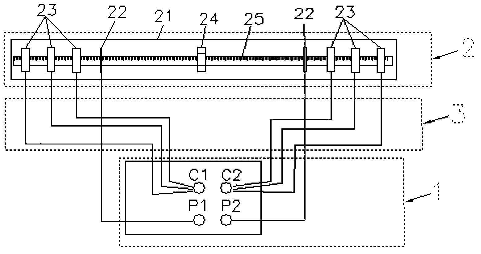
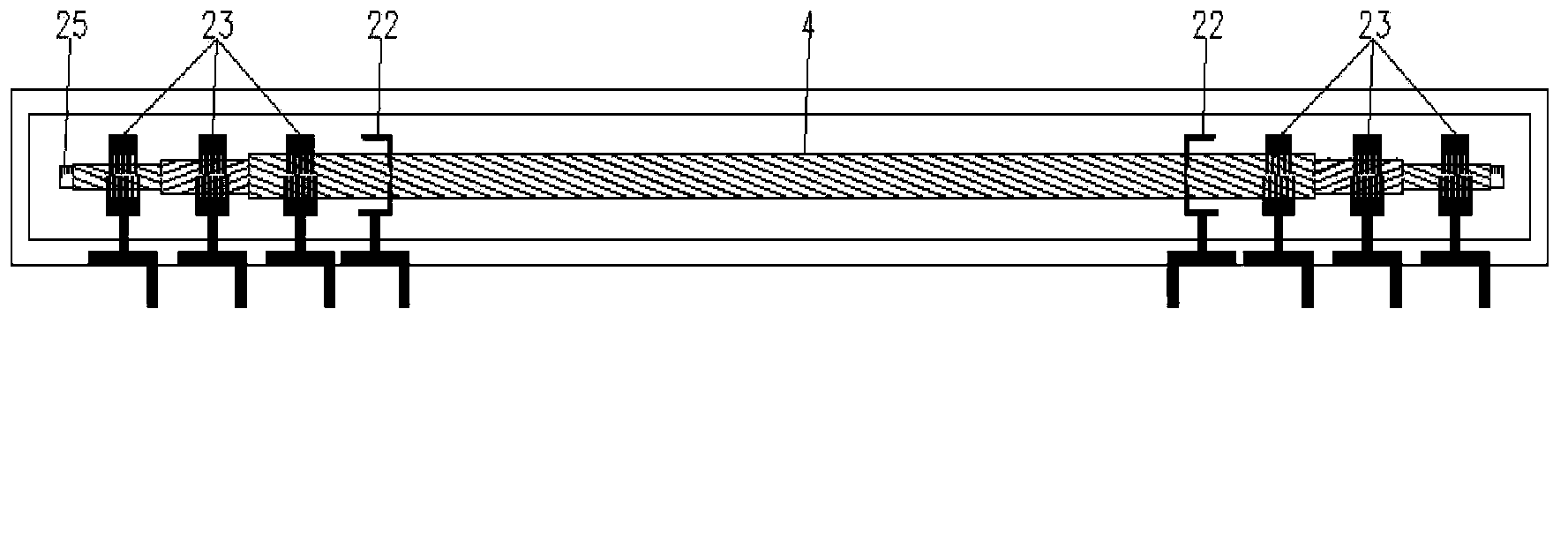
[0029] See figure 1 and figure 2 , the cable conductor DC resistance testing device in this embodiment includes a double-arm bridge 1 , a sample holder 2 and a connecting wire 3 that electrically connects the two. The sample holder 2 includes a base 21 with a scale 25 , a voltage electrode holder 22 , a current electrode holder 23 , a support bracket 24 and a scale 25 . The voltage electrode clamp 22 and the current electrode clamp 23 are detachably assembled on the base 21 and slidably fixed to the base 21 . Of course, one end can be fixed and the other end can be slidably fixed. The voltage electrode clamps 22 and the current electrode clamps 23 are arranged in pairs at both ends of the base 21; the current electrode clamps 23 are at least two pairs, and the specific number of pairs is equal to the number of layers of the conductors of the cable to be tested, and the current electrodes located on the same side of the base 21 The clamps 23 are connected two by two. Each o...


PUM


Abstract

The invention discloses a cable conductor DC-resistance testing device and a testing method. The testing device includes a double-arm electrical bridge, a sample clamping seat and a connection wire which electrically connects the double-arm electrical bridge and the sample clamping seat. The sample clamping seat includes a base with a scale, voltage electrode clamps and current electrode clamps. The voltage electrode clamps and the current electrode clamps can be fixed in a slide manner on the base. The device and the method adopt improvement of the length of a tested sample and a layered current input method to test the DC resistance of a conductor so that effects of contact resistance on a testing result can be reduced and thus untruthfulness DC-resistance testing data of the conductor is prevented and accuracy of the test is improved.

Description

technical field [0001] The invention relates to a cable conductor direct current resistance testing device and a testing method using the device. Background technique [0002] The equipment for measuring the DC resistance of conductors is currently a two-arm bridge. The fixture used is generally a four-terminal measuring fixture, a pair of potential electrodes and a pair of current electrodes, and the distance between the potential electrodes is fixed at one meter. This measuring device is for less than 50mm 2 For the following conductors, the error in the test is very small and can be basically ignored. However, when testing large-sized conductors, especially large-sized aluminum conductors, it is often found that the detection error is large, the fluctuation of multiple measurement data is large and unstable, and the test data is untrue, etc. Phenomenon. When producing conductors, manufacturers find that the cross-section and single-wire resistivity of conductors are qua...

Claims


Application Information

Patent Timeline
Patent Type & Authority Applications(China)
IPC IPC(8): G01R27/08
Inventor 徐静蒋华娟
Owner FAR EAST CABLE
Why Eureka
Try Eureka