System and method for stripping optical cable

An optical cable and laser technology, applied in the installation of cables, coupling of optical waveguides, optics, etc., can solve the problems of idle equipment, low equipment stability, limited service life of blades, etc., to improve efficiency, avoid blade losses and limitations , the effect of improving stability

Inactive Publication Date: 2014-05-07
ADC TELECOMM (SHANGHAI) DISTRIBUTION CO LTD
View PDF8 Cites 6 Cited by
  • Summary
  • Abstract
  • Description
  • Claims
  • Application Information

AI Technical Summary

Problems solved by technology

[0005] In addition, due to the use of blades in the existing technology, and the service life of the

Method used


Image

  • System and method for stripping optical cable
  • System and method for stripping optical cable
  • System and method for stripping optical cable

Examples


Embodiment Construction

[0022] Exemplary embodiments of the present invention are described in detail below, examples of which are illustrated in the accompanying drawings, wherein the same or similar reference numerals refer to the same or similar elements. The embodiments described below with reference to the accompanying drawings are exemplary and intended to explain the present invention, but not to limit the present invention.

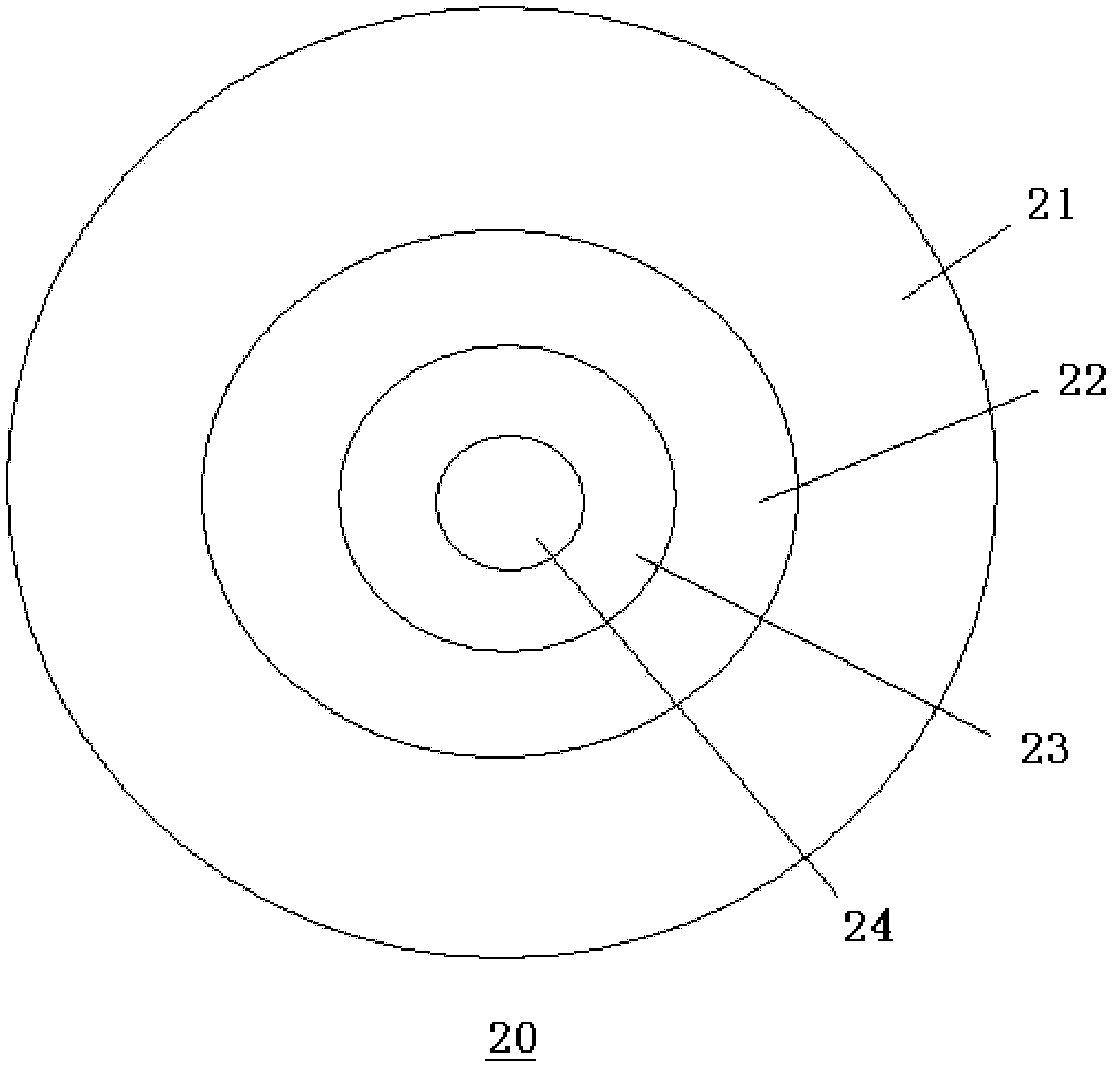
[0023] figure 1 A schematic cross-sectional view of an optical cable according to an embodiment of the present invention is shown in . The optical cable 20 includes, from the outside to the inside, an optical cable sheath 21 , a Kevlar 22 , a 900 μm coating layer (including a buffer layer) 23 , and a bare fiber 24 . It should be pointed out that the structure of the optical cable mentioned above is only exemplary.

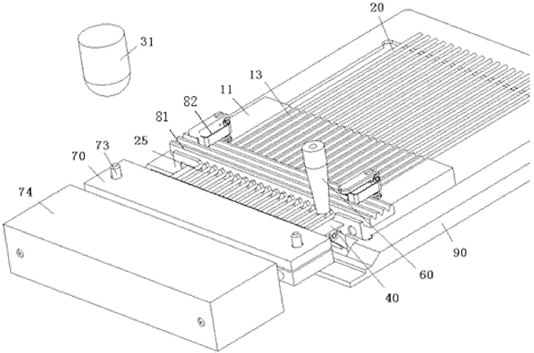
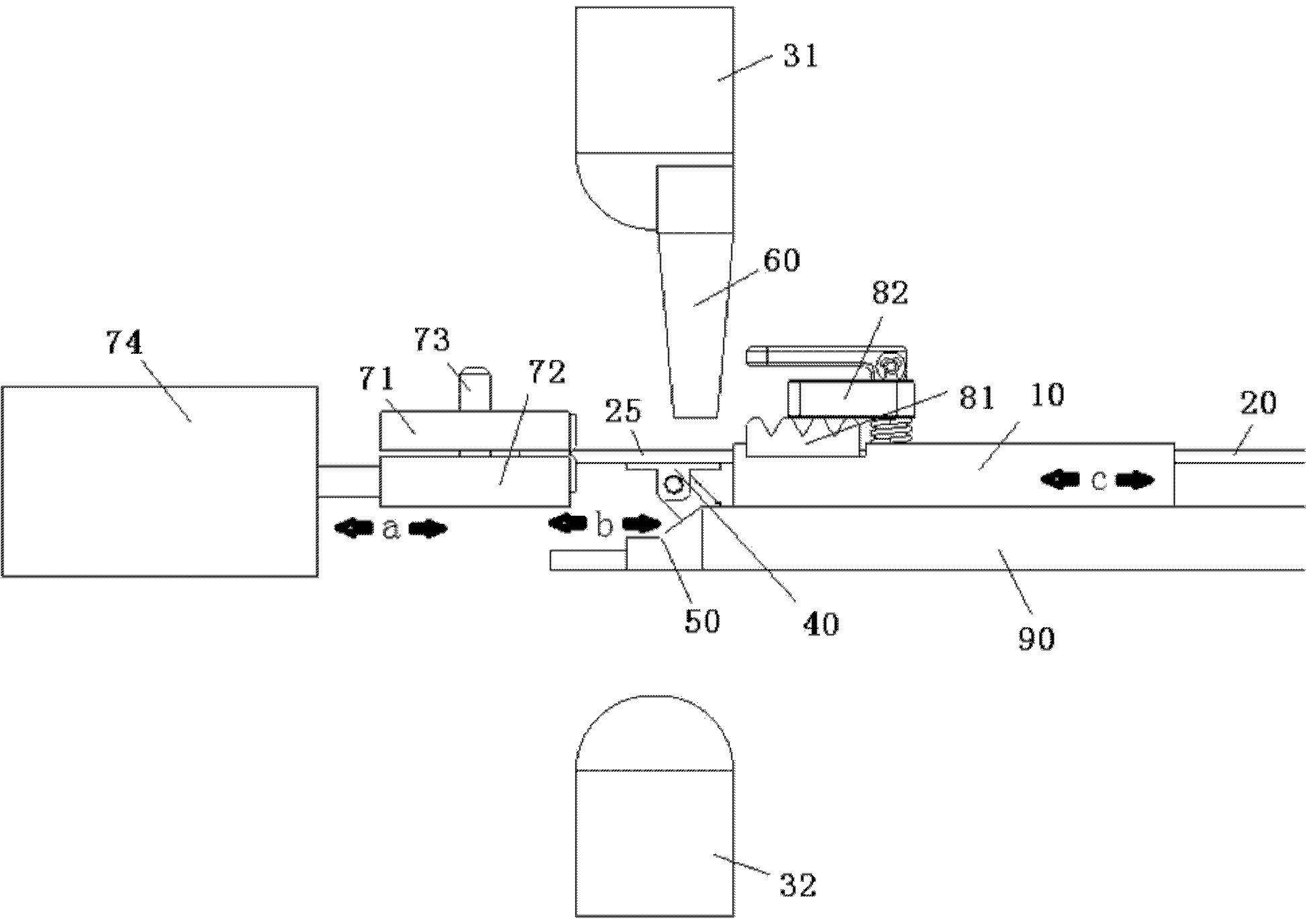
[0024] Refer below Figure 2-4 A system for stripping optical cables according to one embodiment of the present invention is described. The system includ...


PUM


Abstract

The invention relates to a system for stripping an optical cable. The optical cable (20) includes a bare fiber (24), a coverage layer (23) wrapping the bare fiber, a Kevlar layer (22) and an optical-fiber protective sleeve (21) from inside to outside. The system includes an optical-cable loading bench (10) provided with an end face (12) and an optical-cable loading face (11), wherein the optical-fiber loading face (11) is structured to be suitable for fixing the optical cable to be stripped on the loading face of the optical-cable loading bench and an to-be-stripped end of the optical cable extends out of the end face of the optical-cable loading bench; an air injection device (60) suitable for blowing air to the Kevlar exposed at the to-be-stripped end so as to make the Kevlar separate from the bare fiber; and a cutting device used for cutting the separated Kevlar. The invention also relates to an optical-cable stripping method.

Description

technical field [0001] The present invention relates to the stripping of optical cables, and more particularly to methods and systems for stripping optical cables. Background technique [0002] The current technology for stripping optical cables uses semi-automatic mechanical blades to cut cable jackets and KEVLAR. During the operation of cutting the jacket of the fiber optic cable, one fiber optic cable is first put in at a time, and then the switch is triggered to cause the automatic blade to peel off the jacket. During the Kevlar cutting operation, one fiber optic cable is put in at a time, and the switch is triggered to cause the automatic blade to cut through the Kevlar. [0003] However, when cutting Kevlar, it is necessary to separate the Kevlar from the bare fiber first, and the separation process is relatively troublesome. [0004] In addition, during the operations of stripping the sheath of the optical cable and cutting the Kevlar, one optical cable is inserted ...

Claims


Application Information

Patent Timeline
IPC IPC(8): G02B6/245G02B6/25G02B6/44
CPCG02B6/00H02G1/128H02G1/1256G02B6/245
Inventor 李航袁拥军冷宗圣吕建春
Owner ADC TELECOMM (SHANGHAI) DISTRIBUTION CO LTD
Why Eureka
Try Eureka