Improved multi-scale finite element method for stimulating two-dimensional water flow movement in porous media

A porous medium and finite element technology, applied in the field of hydraulics, can solve problems such as unsteady flow, achieve the effect of reducing the amount of calculation and calculation time, and high efficiency

Active Publication Date: 2014-05-07
NANJING UNIV
View PDF1 Cites 12 Cited by
  • Summary
  • Abstract
  • Description
  • Claims
  • Application Information

AI Technical Summary

Problems solved by technology

[0010] Aiming at the deficiencies in the prior art, the present invention provides an improved multi-scale finite element method for simulating two-dimensional water flow motion in porous media, which can be applied to solve the water flow problems of steady flow and unsteady flow

Method used


Image

  • Improved multi-scale finite element method for stimulating two-dimensional water flow movement in porous media
  • Improved multi-scale finite element method for stimulating two-dimensional water flow movement in porous media
  • Improved multi-scale finite element method for stimulating two-dimensional water flow movement in porous media

Examples


Embodiment 1

[0034] Embodiment 1: the continuum model of two-dimensional steady flow

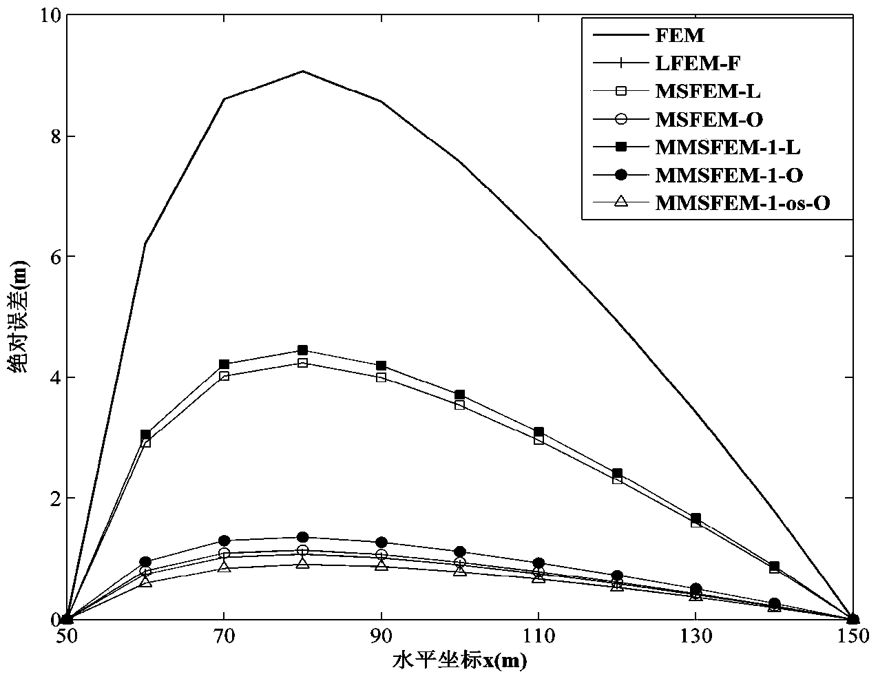
[0035] The research area is a square unit: Ω=[50m, 150m]×[50m, 150m], permeability coefficient K(x,y)=x 2 m / d. The water flow equation is formula (1), and the boundary condition is constant head boundary condition This model has an analytical solution: H=3x 2 +y 2 .

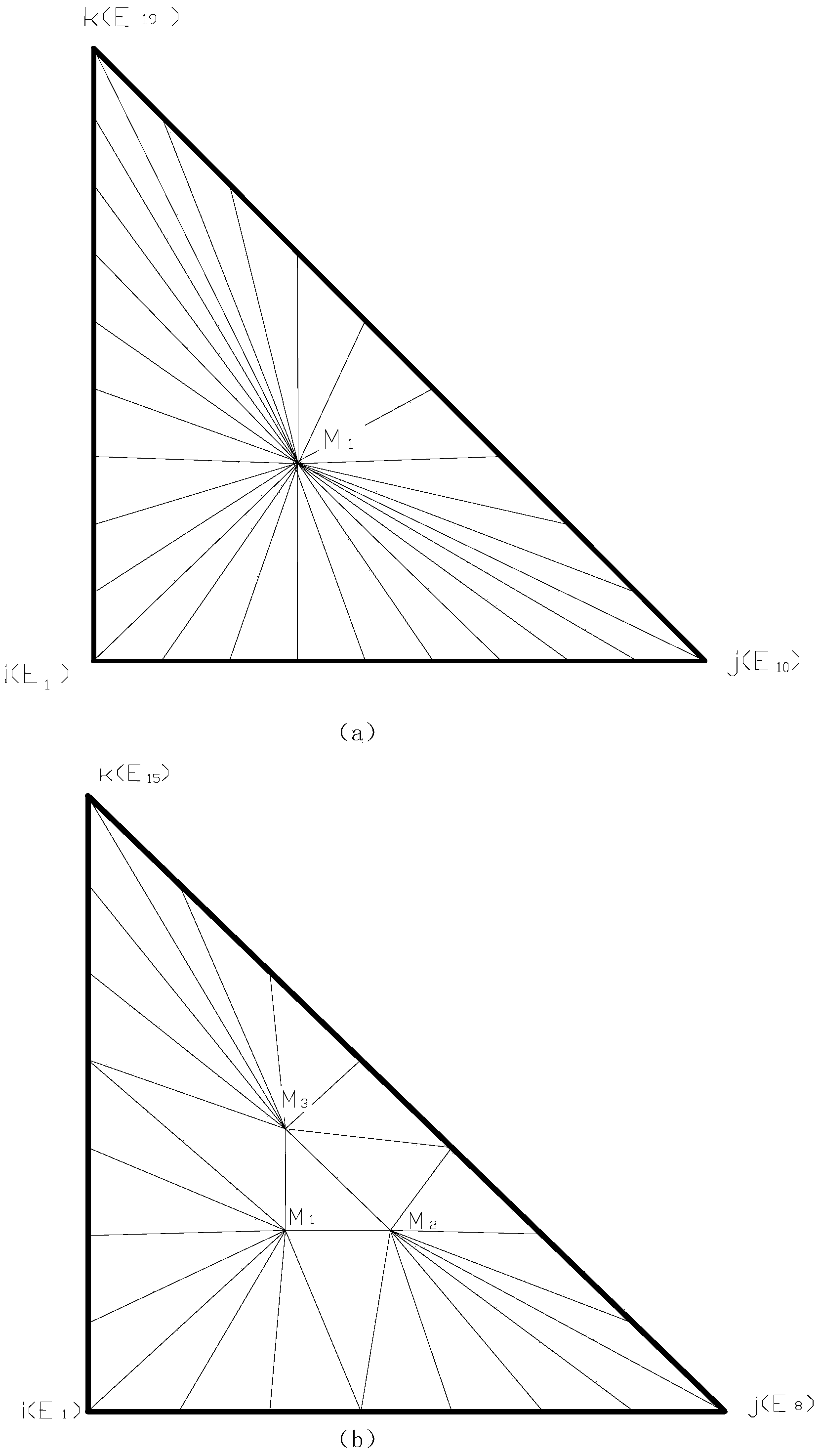
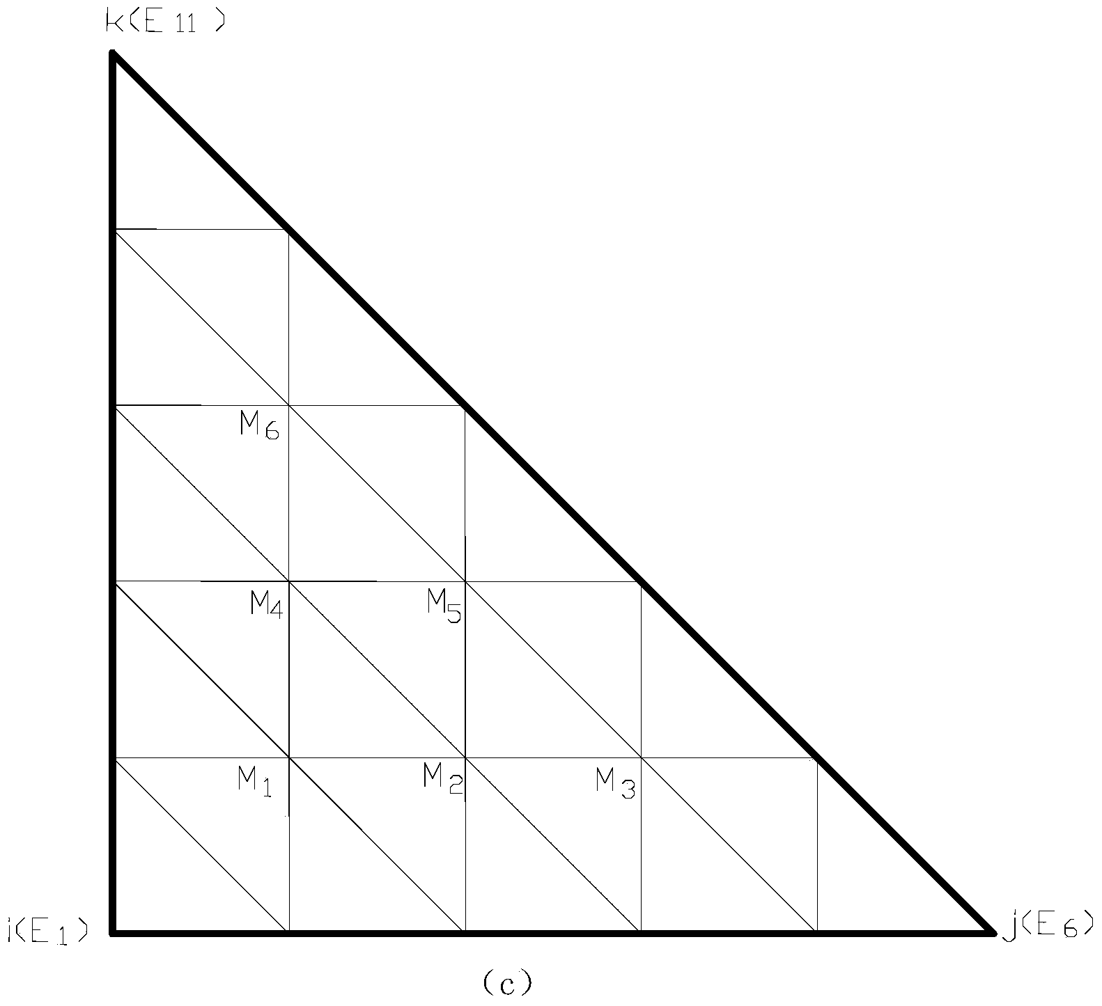
[0036] The model is solved by LFEM, LFEM-F, MSFEM-L, MSFEM-O, MMSFEM-1-L, MMSFEM-1-O, MMSFEM-1-os-O. Among them, LFEM-F divides the study area into 1800 parts, and other methods divide the study area into 200 coarse grid units. MSFEM uses the traditional triangulation method to subdivide each coarse grid into 9 units, and MMSFEM adopts the improved fine subdivision method to subdivide each coarse grid into 9 units. The super sample unit used by the super sample technology is 1.01 times of the coarse grid unit.

[0037] figure 2 For the head calculated by the above method, the absolute error of the profile at y=100m. From figure 2...

Embodiment 2

[0038] Example 2: Gradient medium model of two-dimensional unsteady flow (pumping model of flood plain)

[0039] The research area is a square unit: Ω=[0,10km]×[0m,10km], the permeability coefficient increases from 1m / d to 250m / d from the left side to the right side of the boundary of the research area, namely K(x,y)= 1+x / 40m / d. The water flow equation is formula (2), the left and right boundaries define the water head boundary, the left boundary is 10m, the right boundary is 0m, and the upper and lower water barrier boundaries. The thickness of the aquifer is 10m, and the water storage coefficient S=0.00001-0.000009x / 1000 / m. There is a pumping well at coordinates (5200m, 5200m) with a flow rate of 1000m 3 / d, the pumping time is 5 days, and the time step is 1 day. The water head H at the initial moment 0 (x, y) = 10-x / 1000m. There is no analytical solution for this model, therefore, the solution of LFEM-F is used as the standard reference.

[0040] The model is solved b...

Embodiment 3

[0041] Example 3: Two-dimensional unsteady flow abrupt change medium model

[0042] The research area is a square unit: Ω=[0,10km]×[0m,10km], the permeability coefficient changes abruptly at x=2480m, that is, when x3 / d, the pumping time is 3 days, and the time step is 1 day. The thickness of the aquifer is 10m, the water storage coefficient x0 (x, y) = 10-x / 1000m. There is no analytical solution for this model, therefore, the solution of LFEM-F is used as the standard reference.

[0043] Use LFEM, LFEM-F, MSFEM-O, MMSFEM-3-O to solve this model. Among them, LFEM-F divides the study area into 80,000 triangular units, and other methods divide the study area into 400 units. In this model, MMSFEM adopts radial subdivision, and MSFEM adopts traditional subdivision to subdivide the coarse grid unit into 100 triangular units. Figure 4 is the water head of each method y=5000m section. The accuracy of MMSFEM is very close to that of MSFEM. In this model, the CPU time required by...


PUM


Abstract

The invention discloses an improved multi-scale finite element method for stimulating two-dimensional water flow movement in porous media. The method comprises the steps as follows: firstly, converting a problem to be solved into a variational form; determining a boundary condition, setting a grid cell size h, subdividing a research area, and obtaining coarse grid cells; subdividing each coarse grid cell; according to a permeability coefficient K and the boundary condition of a basis function, solving the problem of degenerating elliptic type, and determining the basis function; according to the basis function, obtaining cell stiffness matrixes, and adding the same to obtain a total stiffness matrix; according to the boundary condition of the research area and a source sink term, obtaining a right-hand side; adopting an effective calculating method to solve the simultaneous equations of the total stiffness matrix and the right-hand side; and obtaining the hydraulic heads of all nodes in the research area. Through various simulation tests, the obtained result coincides with the analytical solution. Compared with the prior art, the method disclosed by the invention is similar to the same in precision, but the calculating time of the method is less than 10% of the calculating time in the prior art. The efficiency is greatly improved when the method is used for solving wide-range, long-time or complicated problems.

Description

technical field [0001] The invention relates to the field of hydraulics, in particular to an improved multi-scale finite element method for simulating two-dimensional water flow motion in porous media. Background technique [0002] The issue of water resources is an important issue closely related to human survival. Many cities around the world draw most of their water from groundwater. In addition, in geological engineering activities, the distribution of groundwater is also a factor that must be considered. Therefore, it is of great significance to study the calculation method and simulation of groundwater level for measuring and forecasting the distribution of groundwater. [0003] The general equation of groundwater flow describes the distribution of steady flow by elliptic equation, and its two-dimensional form is: [0004] - ∂ ∂ x ( K xx ...

Claims


Application Information

Patent Timeline
Patent Type & Authority Applications(China)
IPC IPC(8): G06F17/50
Inventor 谢一凡吴吉春薛禹群谢春红吴勤
Owner NANJING UNIV
Why Eureka
Try Eureka