Dynamic capacity increasing method for oil-immersed transformer

An oil-immersed transformer and dynamic capacity-increasing technology, which is applied in the field of transformers, can solve problems such as unfavorable expansion of substation intelligent control and intelligent management, failure to consider the influence of ambient temperature cooling effect, and inability to satisfy the dynamic control of transformers, etc., to achieve reduction Continuous working time, energy-saving operation, and overheating prevention effect

Active Publication Date: 2014-05-07
SHANGHAI MUNICIPAL ELECTRIC POWER CO +1
View PDF7 Cites 44 Cited by
  • Summary
  • Abstract
  • Description
  • Claims
  • Application Information

AI Technical Summary

Problems solved by technology

It performs forced cooling on the transformer blades in order to reduce the operating temperature of the transformer, which is suitable for the transformation of existing transformers, but it only considers the forced cooling of the transformer, and does not consider the influence of the change of ambient temperature on the cooling effect, which is extensive The type of operation mode is not a real energy-saving operation, and it is necessary to add a cooling device to the transformer body, which will be subject to many restrictions such as safety distance and insulation level, which cannot meet the dynamic control of the transformer's operable capacity and real-time control of the transformer's operating status. , which is not conducive to the expansion of substation intelligent control and intelligent management
[0009] At present, the control of foreign transformer cooling methods is adjusted according to the size of the load, that is, the switching off of the cooling fan is controlled according to the size of the load, and the beneficial impact of environmental changes on cooling is not considered.

Method used


Image

  • Dynamic capacity increasing method for oil-immersed transformer
  • Dynamic capacity increasing method for oil-immersed transformer
  • Dynamic capacity increasing method for oil-immersed transformer

Examples


Embodiment Construction

[0069] The present invention will be further described below in conjunction with the accompanying drawings.

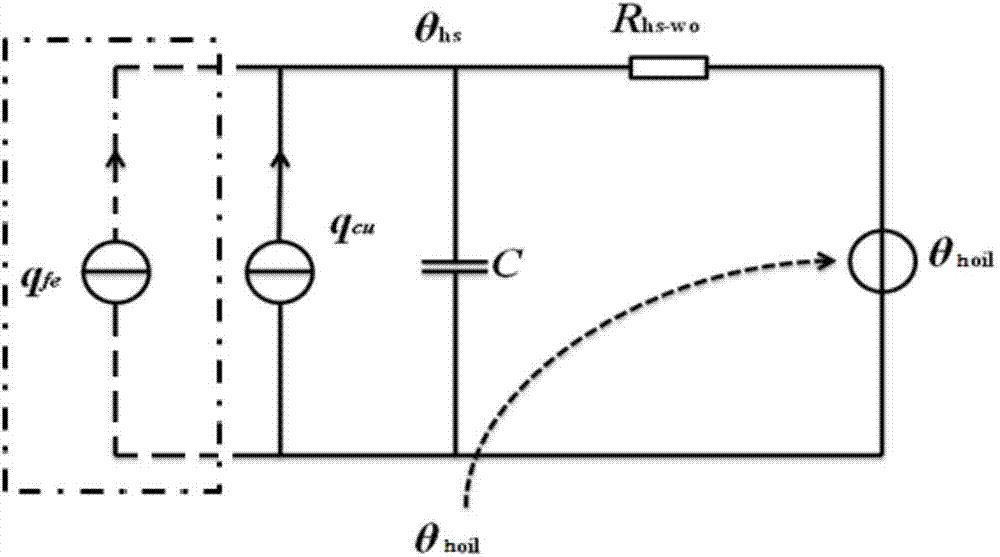
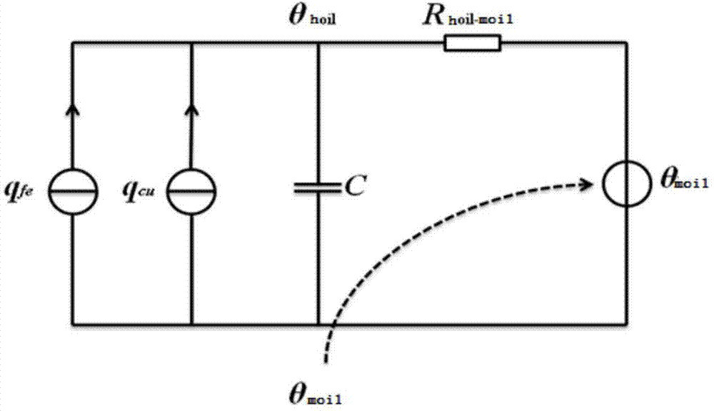
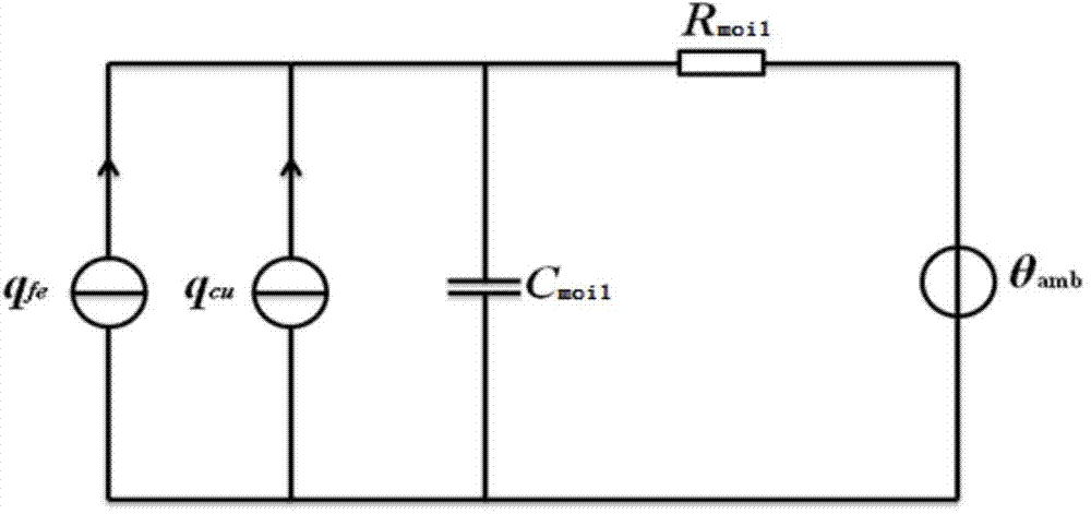
[0070] Figure 1~3 Among them, the improved thermal circuit model of the transformer of the present invention is composed of three sub-thermal circuit models, which are sequentially from top to bottom: the thermal circuit model of the winding hot spot to the top layer oil temperature, the thermal circuit model of the top layer oil to the average oil temperature, and the shell to the ambient temperature Thermal model.

[0071] The node temperature value obtained in the next model can be regarded as the ambient temperature of the previous model, and so on, and finally the hot spot temperature of the winding can be obtained.

[0072] The parameters in each model are adjusted as follows:

[0073] Table 1. Calculation parameter table

[0074]

[0075] Among them, R y is the thermal resistance, C y is the heat capacity, the subscript hs-oil in the parameter indicates...


PUM


Abstract

The invention relates to a dynamic capacity increasing method for an oil-immersed transformer, and belongs to the field of transformers. The method includes the steps that heat conduction process in the transformer is simplified into a circuit model; winding hot-spot temperature, top oil temperature, average oil temperature, average winding temperature of the transformer under the current load condition are calculated; according to the limit that the winding hot-spot temperature does not exceed 140 DEG C, whether temperature in the transformer will exceed the limit temperature or not under the current load and environment conditions is calculated, whether a temperature limit value is reached or not if long-term emergency loads or short-term emergency loads occur at the moment is calculated, and if the temperature in the transformer possibly exceeds the limit value of the short-term emergency loads, the time for reaching the limit value and the finally reached steady state temperature are calculated to serve as alarm signals; if it is monitored that the temperature will exceed the standard within t minutes, an early-warning signal is sent out, certain time delay is set, and if the loads are not reduced within the set time delay, a cooling fan of the transformer is turned on. Long-term continuous operation of cooling equipment can be avoided, and operation life of the cooling equipment is prolonged.

Description

technical field [0001] The invention belongs to the field of transformers, in particular to a dynamic capacity increasing method for oil-immersed transformers. Background technique [0002] With the rapid development of the power system, the capacity increase of power transmission and transformation equipment has been widely concerned. [0003] As the core equipment of power transmission and transformation, power transformers currently have their normal operating capacity far below the rated capacity (generally less than 50% of the rated capacity), and the equipment is far from being effectively utilized. Therefore, on the premise of not affecting the service life of the transformer, increasing the operating capacity of the transformer can not only meet the requirements of power supply capacity, but also effectively reduce the investment in equipment. [0004] The reason a transformer is run at a much lower capacity than its rated capacity is for safety reasons. Power syst...

Claims


Application Information

Patent Timeline
Patent Type & Authority Applications(China)
IPC IPC(8): H01F41/00G01K13/00
Inventor 魏本刚李红雷王黎明
Owner SHANGHAI MUNICIPAL ELECTRIC POWER CO
Why Eureka
Try Eureka