Field emission light source

A field emission and light source technology, applied in the direction of fluorescent screen lamps, lamp parts, etc., can solve the problems of unevenness, performance degradation, micro-tip damage, etc., and achieve the effect of stable light emission

Inactive Publication Date: 2014-05-07
OCEANS KING LIGHTING SCI&TECH CO LTD +2
View PDF0 Cites 0 Cited by
  • Summary
  • Abstract
  • Description
  • Claims
  • Application Information

AI Technical Summary

Problems solved by technology

[0005] However, with the current preparation technology, under the action of a strong electric field, the problems of micro-tip damage, current fluctuation, and performance degradation have not been completely resolved. Therefore, the traditional field emission light source has the disadvantages of unstable and uneven light emission.

Method used


Image

  • Field emission light source
  • Field emission light source
  • Field emission light source

Examples


Embodiment 1

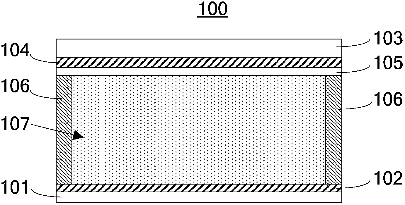
[0043] Such as figure 2 The field emission light source 100 shown includes a cathode substrate 101 , a cathode conductive layer 102 , an anode substrate 103 , an anode conductive layer 104 , a light emitting layer 105 , side walls 106 , a sealed cavity 107 and nitrogen gas 108 . Wherein, the material of the cathode substrate 101 is transparent glass; the material of the cathode conductive layer 102 is an ITO film with a thickness of 1 μm; the material of the anode substrate 103 is transparent conductive glass; the material of the anode conductive layer 104 is an ITO film with a thickness of 1 μm; Layer 105 is Y 2 o 3 :Eu, Y 2 SiO 5 :Tb and Y 2 SiO 5 :Ce is a three-color phosphor that emits white light and is a mixture of the three.

[0044] The cathode conductive layer 102 and the cathode substrate 101 are stacked. The anode substrate 103, the anode conductive layer 104 and the light emitting layer 105 are stacked in sequence. The cathode conductive layer 102 and the li...

Embodiment 2

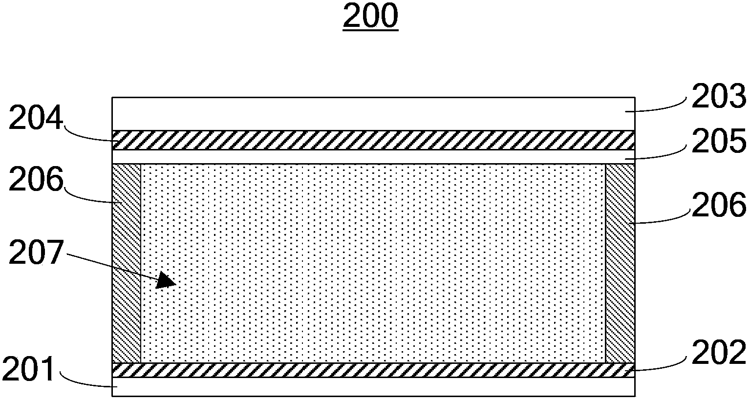
[0048] Such as image 3 The structure of the field emission light source 200 shown is similar to that of the first embodiment. The field emission light source includes a cathode substrate 201, a cathode conductive layer 202, an anode substrate 203, an anode conductive layer 204, a light emitting layer 205, a side wall 206, a sealed cavity 207 and a mixed gas 208 of nitrogen and helium. Wherein, the material of the cathode substrate 201 is transparent ceramics; the material of the cathode conductive layer 202 is an aluminum film with a thickness of 4 μm; the material of the anode substrate 203 is transparent conductive glass; the material of the anode conductive layer 204 is a molybdenum film with a thickness of 4 μm; Layer 205 is Y 2 o 2 S: Eu phosphor.

[0049] The cathode conductive layer 202 and the cathode substrate 201 are stacked. The anode substrate 203, the anode conductive layer 204 and the light emitting layer 205 are stacked in sequence. The cathode conductive ...


PUM


Abstract

The invention discloses a field emission light source comprising sidewalls, a cathode substrate, an anode substrate, a cathode conducting layer, an anode conducting layer, and a light emitting layer. A sealed cavity is formed by the sidewalls, the cathode substrate, and the anode substrate and is fully filled with neutral gases. The neutral gases comprise at least one of a group including hydrogen, nitrogen, helium, and argon. The cathode conducting layer and the cathode substrate are arranged in a laminated manner. The anode substrate, the anode conducting layer, and the light emitting layer are successively arranged in a laminated manner. The cathode conducting layer and the light emitting layer are arranged oppositely and the light emitting layer contacts the neutral gases directly. The sealed cavity of the field emission light source is fully filled with the neutral gases used as an electron source. High voltage is applied to the anode conducting layer and the cathode conducting layer such that the neutral gases in the sealed cavity are ionized to form positive ions and free electrons. The light emitting layer is bombarded by the free electrons so as to emit visible light. Thus, the field emission light source emitting stable and uniform light is obtained.

Description

technical field [0001] The invention relates to an illumination light source, in particular to a field emission light source. Background technique [0002] Artificial lighting sources can generally be divided into incandescent lamps, discharge lamps and solid-state light sources, including incandescent lamps, fluorescent tubes, LEDs, halogen lamps, high-pressure gas discharge lamps, etc. Incandescent lamps generate heat and emit light after the tungsten wire is electrified, which not only has low luminous efficiency but also generates a lot of heat at the same time. Fluorescent tubes have high luminous efficiency, but contain mercury, which is harmful to the environment and human body, and is not suitable for environmental protection requirements. Solid-state light sources such as LEDs also have problems such as self-scattering, rapid life decay in high-temperature environments, and poor fiber divergence. [0003] Field emission light source (Field emission light source) i...

Claims


Application Information

Patent Timeline
Patent Type & Authority Applications(China)
IPC IPC(8): H01J63/06H01J63/02
Inventor 周明杰徐习贤陈贵堂
Owner OCEANS KING LIGHTING SCI&TECH CO LTD
Why Eureka
Try Eureka