Electric stapler

A stapler and electric technology, applied in the direction of endoscopic cutting instruments, surgical fixation nails, etc., can solve the problems of manual safety control device, increased volume, increased cost, increased use cost, etc., so as to improve the probability of success and reduce the processing cost. , the effect of high practicability

Active Publication Date: 2014-05-14
TIANJIN RAPID PRECISION MACHINERY TECH RES & DEV
View PDF5 Cites 15 Cited by
  • Summary
  • Abstract
  • Description
  • Claims
  • Application Information

AI Technical Summary

Problems solved by technology

[0004] However, the above-mentioned two driving motors and two transmission mechanisms are complicated and difficult to operate. When the kiss cut needs to be fired, two buttons need to be pressed at the same time, which is easy to cause linkage or interference, and

Method used


Image

  • Electric stapler
  • Electric stapler
  • Electric stapler

Examples


Embodiment Construction

[0023] The present invention will be described in further detail below in conjunction with the accompanying drawings and specific embodiments. It should be understood that the specific embodiments described here are only used to explain the present invention, not to limit the present invention.

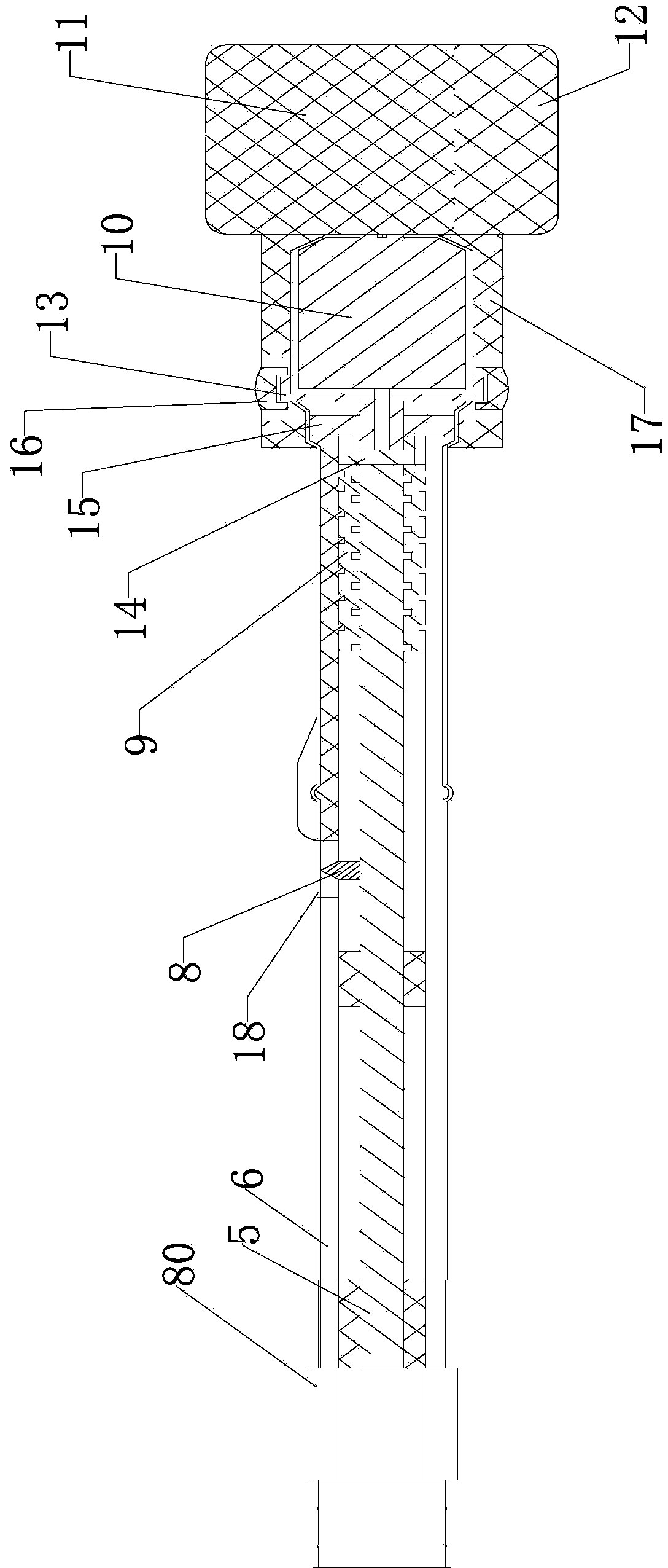
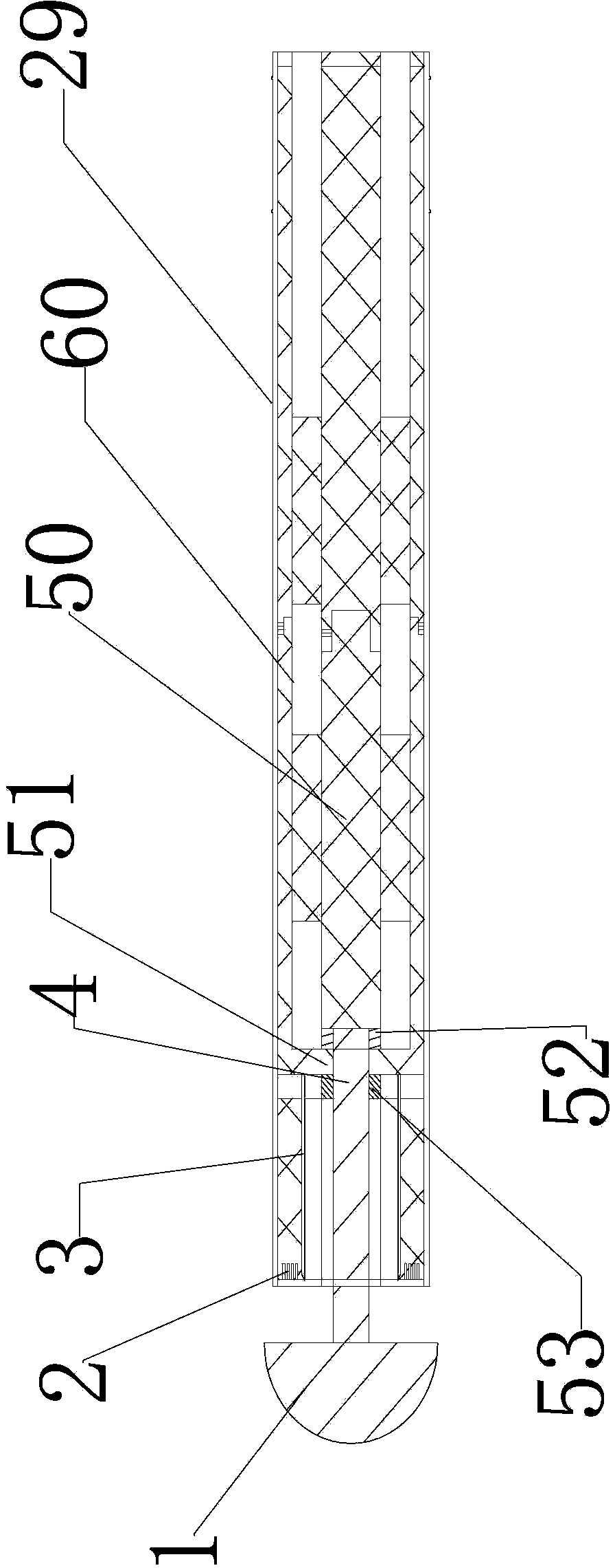
[0024] Such as figure 1 As shown, the electric stapler of the present invention includes a kiss cutting mechanism and a driving actuator, and the driving actuator includes a rear end driving mechanism and a front end actuator connected by a quick connection mechanism, and the rear end driving mechanism includes The tube body 20, the push-back tube 6 set inside the back tube body 20 and driven to screw forward, and the rear center rod 5 arranged at the center of the push-back tube 6 and driven to screw forward and backward; the front end implements The mechanism includes a front tube body 29, a forward push tube 60 arranged inside the front tube body and driven forward and backward, a...


PUM


Abstract

The invention discloses an electric stapler comprising an osculating mechanism and a drive actuator. The drive actuator comprises a rear drive mechanism and a front actuator connected through a quick connection mechanism. The rear drive mechanism comprises a rear pipe, a rear push pipe, and a rear central rod; the rear push pipe is disposed inside the rear pipe and can be driven to screw back and forth; the rear central rod is disposed at the center of the rear push pipe and can be driven to screw back and forth. The front actuator comprises a front pipe, a front push pipe, and a front central rod; the front push pipe is disposed inside the front pipe and can be driven to screw back and forth; the front central rod is disposed inside the front push pipe and can be driven to screw back and forth. The quick connection mechanism comprises a sleeve, first grooves and ribs, and second grooves and ribs; the front and rear pipes are fixedly connected through the sleeve; the first grooves and ribs are arranged on opposing faces of the front and rear push pipes correspondingly; the second grooves and ribs are arranged on the opposing faces of the front and rear central rods correspondingly. The electric stapler is simple in structure and highly practicable, an osculating head can be changed fast, the rear of the stapler can be reused, and usage cost can be reduced.

Description

technical field [0001] The invention relates to the technical field of medical instruments, in particular to an electric stapler. Background technique [0002] The medical stapler is a medical device that is often used when performing surgical operations on the physiological tissues of the digestive tract. Now the commonly used staplers are all manually operated in the process of "closing, stapling, and cutting" the physiological tissues. Usually, the manual operation steps It is cumbersome, prone to misoperation, or causes surgical failure. In addition, due to individual differences, the degree of tissue closure and closure time are likely to be inconsistent during manual closing operations, and the firing force during firing operations will vary greatly, thereby reducing the quality of surgery. [0003] In order to overcome manual deficiencies, Chinese patent 201110109722.7 discloses a surgical electric stapler, which includes an anastomotic part with an abutment seat, a ...

Claims


Application Information

Patent Timeline
IPC IPC(8): A61B17/072A61B17/115
CPCA61B17/07207A61B17/1155A61B17/320016
Inventor 马立军郭庆鹏
Owner TIANJIN RAPID PRECISION MACHINERY TECH RES & DEV
Why Eureka
Try Eureka